My Projects
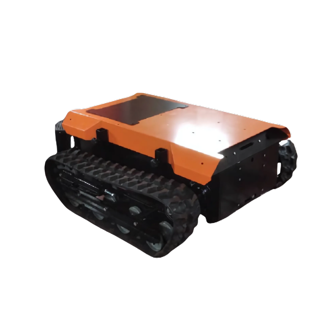
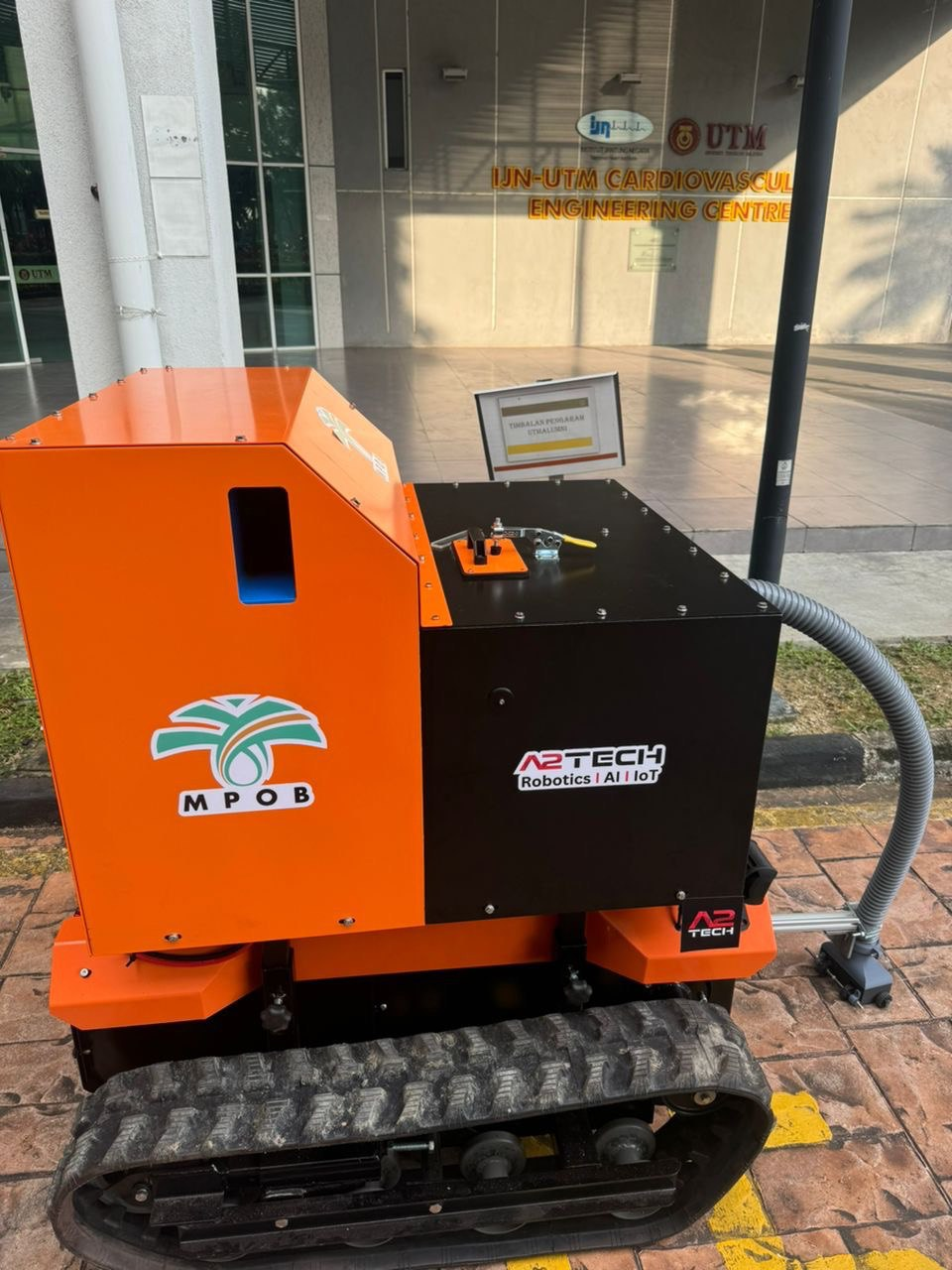
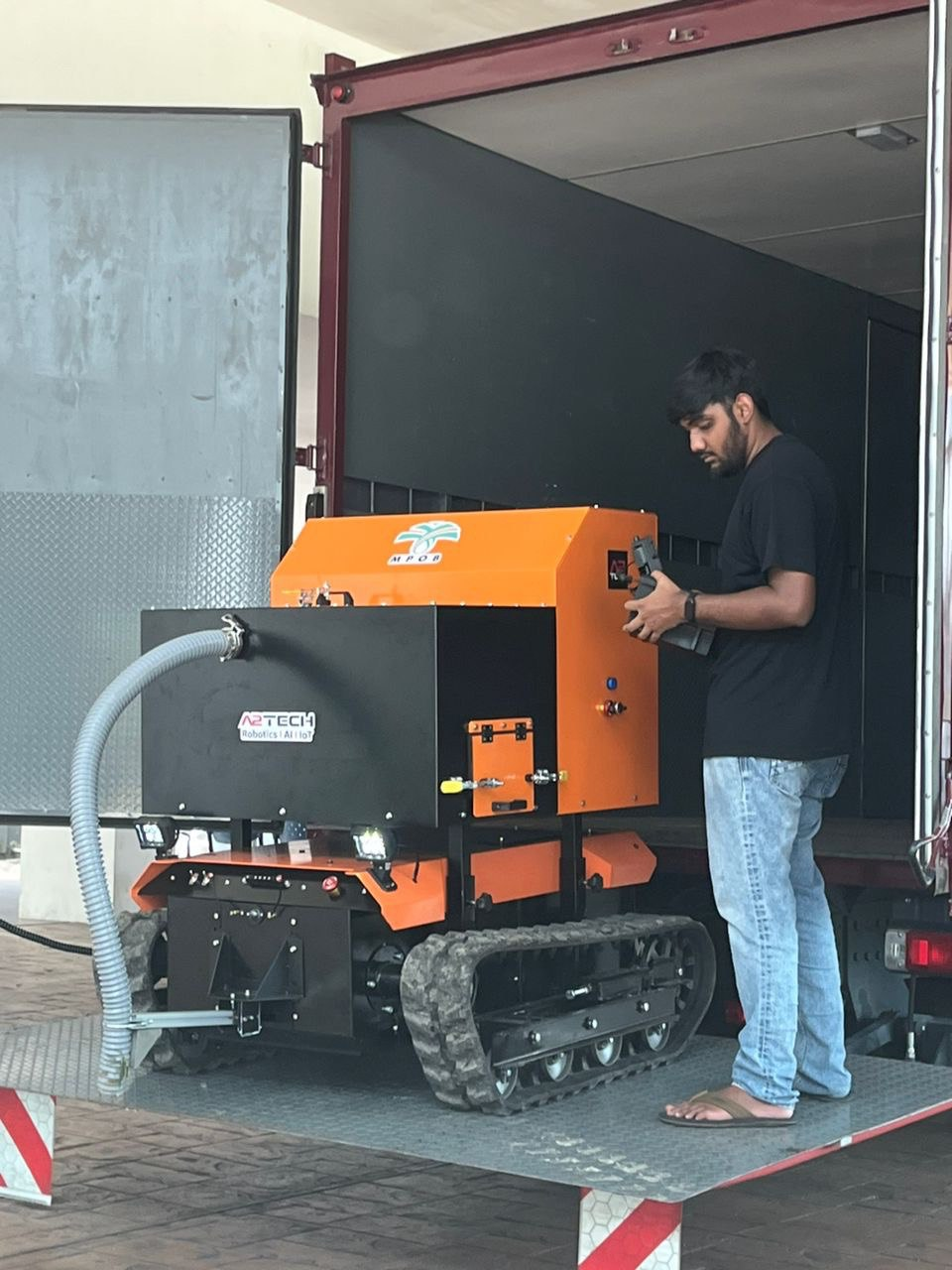
RHINO UGV Platform for MPOB
PCB Design and Circuit Simulation
The RHINO UGV platform featured a custom-designed multi-layer PCB powered by an STM32F407 microcontroller, integrating high-current MOSFET-based power switches, motor driver circuits, and comprehensive communication interfaces, including CANBUS, RS232, and RS485. Circuit simulations were performed to ensure power stability, effective thermal management, and signal integrity, meeting the operational demands of the UGV's robust functions.
Control and Navigation Systems
The RHINO UGV's control system was designed to manage the main platform and modular components, such as the vacuum system for collecting loose palm fruits. The STM32F407-based control board executed motor control, switching, and intensity regulation for the vacuum module, as well as arm control for precise fruit collection. The system was built to withstand heavy operational demands, controlling the robot's powerful propulsion system to carry loads up to 500 kg at a 25-degree incline for continuous 6-hour climbs. Communication options included RC control for basic operations and a 1.4 GHz radio for real-time camera feed transmission.
Electrical and Embedded System Design
The electrical system was developed to handle high current loads and maintain reliable performance during extended operation. High-current MOSFET-based switches managed power distribution, while motor driver circuits powered the robust propulsion needed for heavy load transport. The STM32F407 microcontroller ensured precise real-time control over motors and sensors, integrating CANBUS, RS232, and RS485 for seamless communication. Safety features and power management protocols were included to maintain operational reliability in demanding field conditions.
Communication Systems
The RHINO UGV featured a multi-mode communication system to support flexible operations. RC control was employed for manual operation, and a high-bandwidth 1.4 GHz radio system provided reliable video transmission for remote monitoring. Additionally, a mesh communication network was integrated to ensure stable data transmission within palm fruit field canopies, maintaining connectivity in areas with potential signal obstructions. The ability to switch between communication modes enabled the UGV to adapt to various field conditions and operator preferences.
Sensor Integration and Data Acquisition
The UGV was equipped with a suite of sensors for comprehensive data collection and field operation support, including load sensors, high-resolution cameras, and environmental sensors for terrain analysis. The STM32F407-based control board processed sensor data and managed the vacuum system's operation, including suction intensity and arm movement. The communication system, featuring mesh support and the 1.4 GHz radio, facilitated continuous data transmission and provided operators with real-time feedback and video streams for informed decision-making during operations.
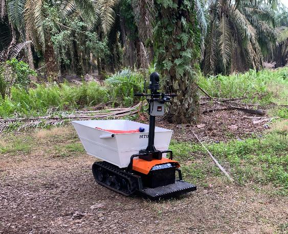
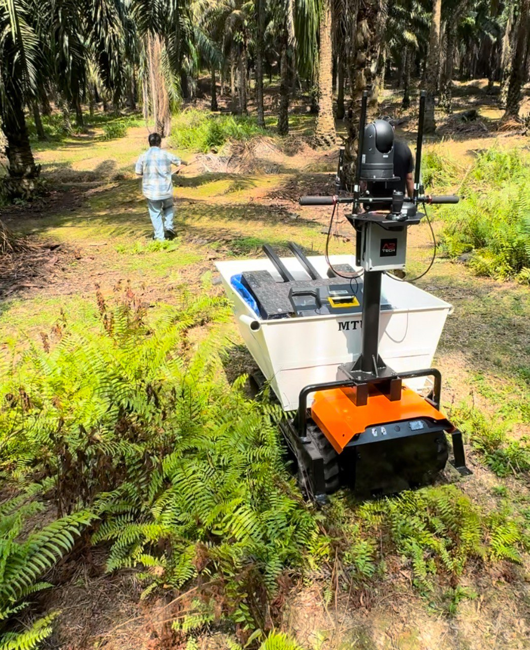
RHINO-F UGV for Palm Fruit Carriage
PCB Design and Circuit Simulation
The RHINO-F UGV was built with a custom-designed multi-layer PCB based on the STM32F407 microcontroller, replicating the reliable architecture used in previous projects. The board integrated high-current MOSFET-based power switches, motor driver circuits, and interfaces for CANBUS, RS232, and RS485 communication. Circuit simulations were performed to ensure power stability, signal integrity, and thermal performance, meeting the high-current demands of the UGV's operation.
Control and Navigation Systems
The RHINO-F was designed to carry loads up to 500 kg and sustain continuous operation on a 20-degree incline for up to 6 hours. The STM32F407-based custom board managed motor control and communication with connected modules. A joystick connected to the onboard Raspberry Pi (RPI) facilitated manual control, allowing intuitive operation by the user. The RPI also supported AI-based detection and data processing, contributing to enhanced safety and operational efficiency. The PTZ camera provided situational awareness and monitoring capabilities during both manual and semi-autonomous operations.
Electrical and Embedded System Design
The electrical system was engineered to handle high-current operations, ensuring stable power distribution to motors and onboard electronics. The STM32F407 microcontroller oversaw real-time motor control, sensor data handling, and communication. High-current MOSFETs managed power switching effectively, while the motor drivers enabled precise propulsion. The system architecture supported modular integration of peripherals such as the PTZ camera and AI detection module, enhancing overall functionality.
Communication Systems
The RHINO-F featured a versatile communication setup that included RC control for manual operation, a mesh network for local connectivity, and a 1.4 GHz high-bandwidth radio for long-distance data and video transmission. This combination allowed operators to select the most effective communication mode for the environment, ensuring reliable connectivity. The 1.4 GHz radio facilitated real-time video feed transmission from the PTZ camera, providing comprehensive visual monitoring for the operator.
Sensor Integration and Data Acquisition
The UGV was equipped with a PTZ camera for high-resolution visual feedback and integrated with the Raspberry Pi for processing AI-based detection tasks. The joystick connected to the RPI provided manual control input, making the robot responsive and adaptive during field operations. The communication network ensured seamless transmission of sensor data and video feeds to the control station, allowing operators to monitor and adjust the UGV's performance in real time. The STM32F407 board managed data acquisition from various input sources, ensuring precise and adaptive control during demanding tasks.
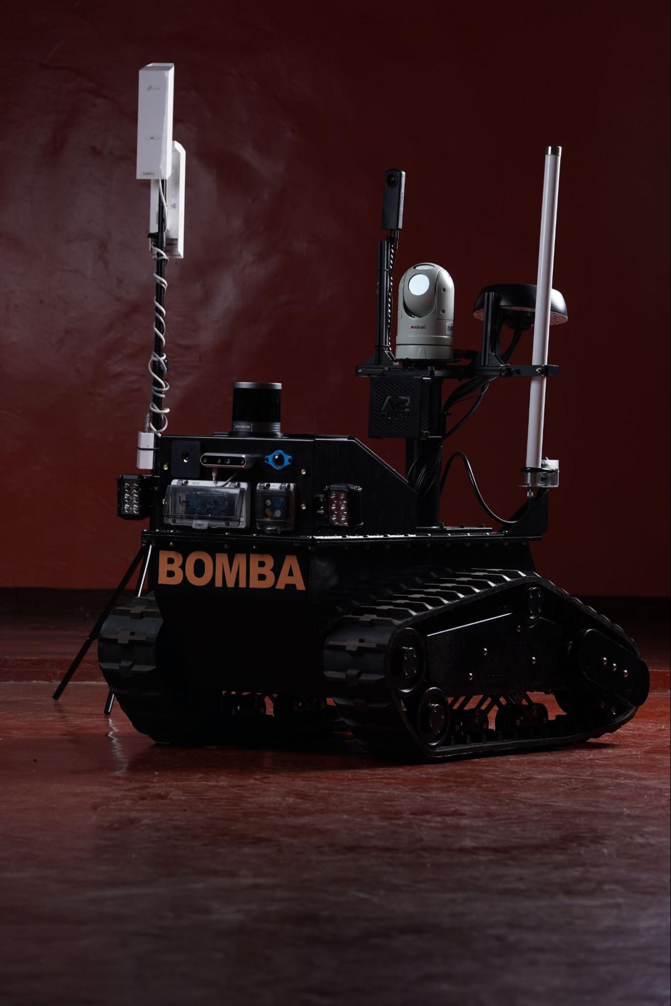
X3CATOR-R Mobile Robot for Malaysian Firefighters

PCB Design and Circuit Simulation
I designed the custom multi-layer PCB that formed the backbone of the X3CATOR-R's embedded control system and sensor integration. The PCB was engineered to interface with various high-powered components, including the motor drivers, power management circuits, and communication modules. Circuit simulation and analysis were performed to ensure power stability, heat management, and signal integrity. The board supported a complex power distribution system that allocated power efficiently to sensors, cameras, and communication modules, ensuring uninterrupted operation during high-demand scenarios.
Control and Navigation Systems
The control system was designed with dual operational modes: RC-based manual control and remote operation from a custom-built control box using high-bandwidth radio communication at 1.4 GHz. This setup provided line-of-sight (LOS) control up to 10 km and non-line-of-sight (NLOS) control up to 1 km within an 11-story building. The embedded system managed real-time processing for navigation, utilizing lidar data for obstacle detection and depth camera input for enhanced spatial awareness. Advanced control algorithms enabled stable maneuvering and precise movement, essential for search and rescue operations in hazardous environments.
Electrical and Embedded System Design
The electrical system design included comprehensive component selection and integration, such as high-power motors, motor drivers, and a reliable power distribution board tailored for the UGV's requirements. The power distribution system was designed to manage load variations and supply stable power to all subsystems, including sensors and cameras. The embedded system featured microcontroller-based architecture, handling sensor fusion, motor control, and communication interfaces. Firmware development focused on real-time task execution, efficient data handling, and the coordination of multiple input sources.
Communication Systems
High-bandwidth radio communication operating at 1.4 GHz was implemented for robust, long-distance control and data transmission. The system supported both LOS communication up to 10 km and NLOS within 1 km in multi-story buildings, ensuring operational flexibility in various terrains and structures. This communication setup facilitated the transfer of video feeds, sensor data, and control commands between the robot and the control box. The control box itself was designed to receive and display real-time sensor data, lidar mapping, and camera feeds, enabling the operator to make informed decisions during rescue missions.
Sensor Integration and Data Acquisition
The X3CATOR-R was equipped with a comprehensive suite of sensors to enhance its capabilities in firefighter support missions. This included a high-resolution PTZ camera with night vision, a thermal camera for heat detection, a 360-degree camera for situational awareness, and depth cameras for navigation in low-visibility conditions. Additional sensors included gas detectors and a radiation sensor for safety monitoring. Data from these sensors were processed and transmitted through the 1.4 GHz communication module to the control box, where real-time displays allowed operators to assess environmental conditions and adjust the robot's behavior accordingly. The lidar system provided detailed mapping for navigation and obstacle avoidance, contributing to the UGV's autonomous and manual operation modes.
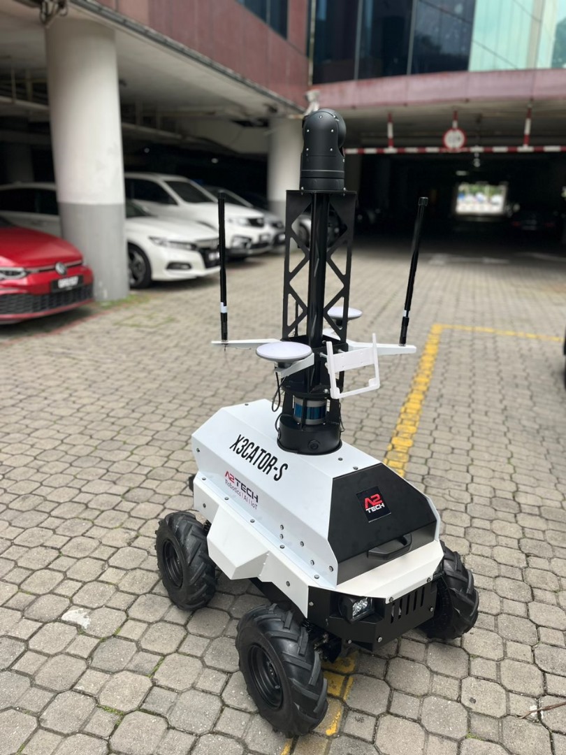
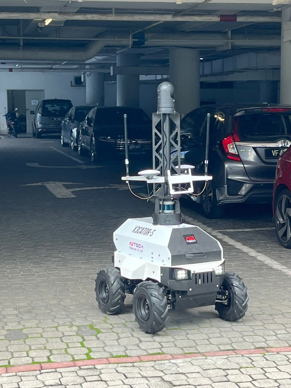
X3CATOR-S Modular UGV Platform
PCB Design and Circuit Simulation
The X3CATOR-S UGV featured a custom multi-layer PCB designed to integrate an STM32H743-based processor for motor control, sensor interfaces, and communication protocols. The PCB included MOSFET-based power switches, motor driver circuits, and interfaces for CANBUS, RS232, and RS485 to support the robot’s complex operations. Circuit simulations were performed to ensure reliable power distribution, signal integrity, and effective thermal management, meeting the high operational requirements of autonomous surveillance.
Control and Navigation Systems
The X3CATOR-S's autonomous system utilized a sophisticated suite of sensors to enable high-precision navigation and environmental awareness. This included a 32-channel lidar for comprehensive 3D mapping and obstacle detection, a depth sensor for terrain assessment, RTK and GNSS modules for centimeter-level positioning accuracy, an IMU for real-time orientation tracking, and GPS for overall navigation assistance. The onboard i7-based computer processed sensor data, performed sensor fusion, and generated control commands. These commands were transmitted to the STM32H743-based PCB, which executed real-time motor control and sensor integration. This combination allowed the UGV to navigate autonomously with high adaptability and precision.
Electrical and Embedded System Design
The electrical architecture included a robust power distribution network managed by MOSFET-based switches, ensuring stable power supply to motors, the onboard i7 computer, and the comprehensive sensor suite. The STM32H743 microcontroller processed control data from the i7 computer, executing precise motor commands and managing real-time data flow from sensors. The embedded system supported modular integration, allowing seamless interfacing with the lidar, depth sensor, RTK/GNSS modules, IMU, and GPS. Safety mechanisms included a bumper-based emergency stop using limit switches to halt operations instantly in case of emergencies.
Communication Systems
The X3CATOR-S incorporated a flexible communication setup featuring RC control for manual operation, a mesh network for local communication, and a high-bandwidth 1.4 GHz radio for long-range data transmission. The 1.4 GHz radio supported LOS communication up to 10 km and NLOS communication up to 1 km, ideal for complex environments such as multi-story buildings. The ability to switch between communication modes allowed operators to select the most suitable method for mission needs, ensuring uninterrupted control and data flow.
Sensor Integration and Data Acquisition
The UGV's sensor array for autonomous operation included a 32-channel lidar for high-resolution 3D mapping, a depth sensor for analyzing terrain features, RTK and GNSS modules for precise positioning, an IMU for orientation tracking, and GPS for general navigation. These sensors provided comprehensive data, which was processed by the i7-based onboard computer to create detailed situational awareness. The STM32H743-based PCB received control commands from the i7 and executed real-time motor control and sensor responses. The communication system facilitated the transmission of processed sensor data and video feeds back to the control station, enabling effective monitoring and decision-making during autonomous surveillance missions.
ROV INSPECTO-UC
PCB Design and Circuit Simulation
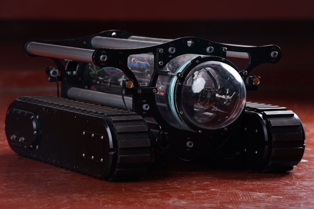
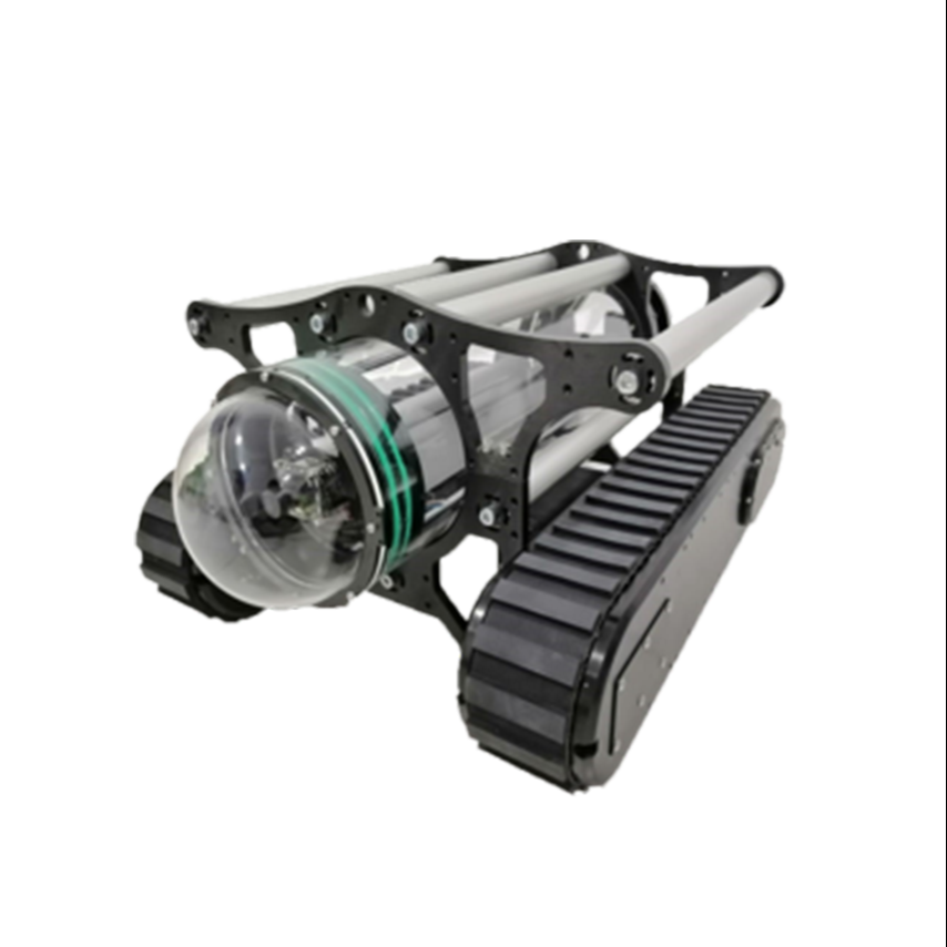
The custom multi-layer PCB design for the ROV INSPECTO-UC included support for the Raspberry Pi (RPI) as the central processing unit, interfacing with dual camera modules, and controlling the external vacuum system. The board featured high-speed signal routing to accommodate video transmission, powerline communication circuits for data exchange, and dedicated motor driver sections for propulsion. Power management circuits and voltage regulators were implemented to ensure stable power distribution across all components, including the high-power external vacuum module. Circuit simulations were performed to verify the integrity of high-speed signals and thermal stability.
Robotics and Autonomous Systems
The ROV INSPECTO-UC was designed as a tether-based underwater cleaning robot, integrating dual cameras for visual monitoring and an external vacuum module for cleaning operations. The RPI acted as the main control unit, managing camera feeds and coordinating the vacuum system alongside the propulsion motors. Powerline communication enabled real-time transmission of video and control signals to the surface control station, overcoming underwater communication challenges. The robot's autonomous capabilities were enhanced by camera-based feedback and sensor data, enabling adaptive navigation and efficient surface cleaning.
Electrical and Embedded System Design
The electrical architecture of the ROV featured a robust power distribution network, supplying stable power to the RPI, camera modules, motor drivers, and the vacuum system. The RPI managed embedded control, including motor actuation and video processing, using its GPIOs and dedicated interfaces. The power system incorporated DC-DC converters for consistent voltage levels, and opto-isolators ensured the safety of the RPI from power spikes. Embedded programming in Python controlled data processing, sensor input handling, and camera streaming, enabling synchronized operation between the propulsion and vacuum systems.
Sensor Integration and Data Acquisition
The ROV was equipped with sensors for depth measurement, IMUs for orientation tracking, and environmental monitoring. These sensors interfaced with the RPI through I2C and UART connections, providing continuous data acquisition for adaptive control. The dual camera setup offered real-time video feedback, aiding in navigation and cleaning verification. The camera feeds, along with sensor data, were transmitted via the powerline communication module to the surface station for operator monitoring and remote control. The seamless integration of these sensors and cameras enabled effective data flow and precision control for underwater surface cleaning tasks.
Control and Navigation Systems
The ROV INSPECTO-UC's control and navigation system was designed to utilize powerline communication for real-time bidirectional data transfer between the underwater vehicle and the base station. The Raspberry Pi onboard acted as the primary processing unit, executing navigation algorithms and motor control for precise maneuvering. The ROV was operated using QGroundControl software on the base station PC, allowing for detailed mission planning, parameter monitoring, and manual overrides. The system incorporated advanced propulsion control through waterproof brushless DC motors, providing stability and adaptability for underwater surface cleaning.
Communication Systems
Powerline communication modules were integrated to facilitate reliable data transfer over the tether, enabling robust communication between the ROV and the base station. This setup supported real-time control commands and the transmission of sensor data, video feeds, and system diagnostics to the operator using QGroundControl. The communication system was optimized for minimal latency, ensuring smooth operation and effective response during mission execution.
ROV INSPECTO-UF2
PCB Design and Circuit Simulation
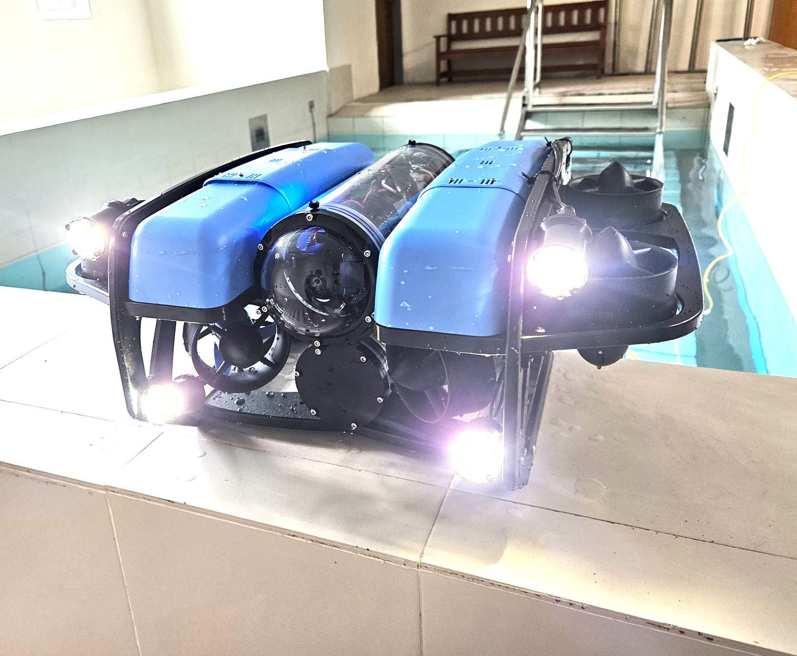
The ROV INSPECTO-UF2 featured a custom multi-layer PCB design to support the onboard Raspberry Pi 5 and Pixhawk flight controller for deep-sea operations. The PCB was engineered for integration with eight thrusters and powerline communication modules, ensuring reliable data transmission over extended distances. Advanced circuit simulations validated signal integrity, power distribution efficiency, and thermal management, essential for withstanding the pressures at a 300-meter depth during surveillance, inspection, and search and rescue missions.
Robotics and Autonomous Systems
Designed as a tether-based underwater vehicle, the ROV INSPECTO-UF2 excels in surveillance, inspection, and search and rescue tasks. The onboard Raspberry Pi 5 handled real-time data processing and coordination with the Pixhawk flight controller for precise navigation. The eight-thruster setup provided superior maneuverability and stability for intricate underwater operations. Powerline communication modules ensured consistent high-bandwidth communication with the surface control station, supporting mission-critical data transfer for video, sensor feedback, and remote command execution.
Electrical and Embedded System Design
The electrical system architecture was designed to deliver high power to the thrusters and ensure stable operation of the onboard computer and communication systems. This included regulated DC-DC converters, power management circuits, and corrosion-resistant components tailored for deep-sea use. Embedded system design integrated the Raspberry Pi 5 as the core processor, enabling real-time control, data acquisition, and communication management. Firmware was developed in Python and C++ to optimize task execution, handle sensor inputs, and manage thruster outputs for adaptive response during surveillance and rescue missions.
Sensor Integration and Data Acquisition
ROV INSPECTO-UF2 was equipped with a range of sensors, including depth sensors, IMUs, and environmental monitoring units, providing real-time situational awareness essential for surveillance, inspection, and search and rescue operations. Sensor data was acquired and processed through the Raspberry Pi 5 and Pixhawk controller, allowing for precise control and quick adaptations. The powerline communication module facilitated seamless transmission of sensor data and video feeds to the surface control station, enabling effective monitoring and decision-making during missions.
Control and Navigation Systems
ROV INSPECTO-UF2 was equipped with a range of sensors, including depth sensors, IMUs, and environmental monitoring units, providing real-time situational awareness essential for surveillance, inspection, and search and rescue operations. Sensor data was acquired and processed through the Raspberry Pi 5 and Pixhawk controller, allowing for precise control and quick adaptations. The powerline communication module facilitated seamless transmission of sensor data and video feeds to the surface control station, enabling effective monitoring and decision-making during missions.
Communication Systems
The ROV's communication system utilized powerline communication modules capable of handling high-bandwidth data transfer over the tether. This configuration supported continuous two-way communication, ensuring that real-time sensor data, video streams, and control commands were effectively relayed between the ROV and the surface control station. QGroundControl facilitated a user-friendly interface for managing these communications, allowing the operator to have complete control over the ROV's functions.
ROV INSPECTO-UF
PCB Design and Circuit Simulation
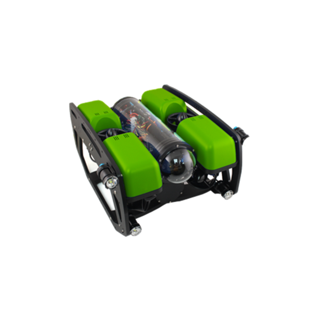
The ROV INSPECTO-UF incorporated a custom-designed multi-layer PCB featuring an STM32H743-based flight controller. This PCB was designed to control all modular functions of the ROV, integrating connections for six thrusters and onboard sensors such as an IMU and depth sensor. High-speed signal routing and powerline communication modules were included for efficient data transmission over the tether. Circuit simulations ensured optimal performance in terms of power distribution, signal integrity, and heat dissipation, crucial for operating at depths of up to 200 meters.
Robotics and Autonomous Systems
This ROV was built for surveillance, inspection, and search and rescue tasks, with AI capabilities for advanced detection and recognition functions. The STM32H743-based custom flight controller managed real-time control and communication, interfacing seamlessly with the six thrusters for enhanced maneuverability and precise operation. The powerline communication module facilitated reliable data exchange with the surface control station. The modular system architecture allowed the ROV to adapt to various mission requirements with efficient task execution and control.
Electrical and Embedded System Design
The electrical system was engineered to support high-power demands while ensuring operational reliability in a 200-meter underwater environment. The custom flight controller incorporated sensor inputs and communication management, with firmware optimized for real-time AI detection and data processing. The embedded system utilized STM32H743 microcontroller capabilities to handle complex control algorithms, thruster coordination, and sensor data processing. Power management circuits included regulated voltage outputs to maintain stability across all connected modules.
Sensor Integration and Data Acquisition
ROV INSPECTO-UF featured integrated sensors, including an IMU and depth sensor directly interfaced with the STM32H743 flight controller for immediate data acquisition and processing. These sensors provided real-time feedback for navigation and operational adjustments. The powerline communication module ensured high-bandwidth transmission of sensor data and AI-processed outputs to the surface station for remote monitoring and control. This seamless data integration enabled the ROV to perform AI-based object detection and respond effectively during surveillance, inspection, and search and rescue operations.
Control and Navigation Systems
The ROV INSPECTO-UF's control and navigation system was built around a custom-made STM32H743-based flight controller, managing real-time motor control, sensor data processing, and navigation tasks. The ROV, equipped with six thrusters, provided dynamic and stable maneuvering, essential for surveillance, inspection, and search and rescue operations at depths of up to 200 meters. The onboard system interfaced seamlessly with QGroundControl software at the base station, giving operators extensive control over mission parameters and real-time navigation.
Communication Systems
Powerline communication was the core of the ROV INSPECTO-UF's data transfer system, ensuring a reliable link between the onboard flight controller and the base station. This communication module allowed real-time command input and feedback, enabling efficient control over long tether lengths. The base station PC, running QGroundControl, received continuous streams of video, sensor readings, and status updates, enabling the operator to make timely decisions and adjustments during operations. This configuration supported both manual and semi-autonomous modes, enhancing operational flexibility and efficiency.
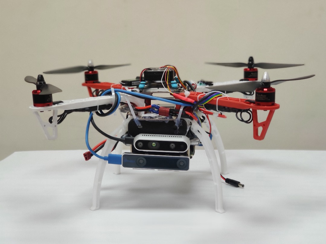
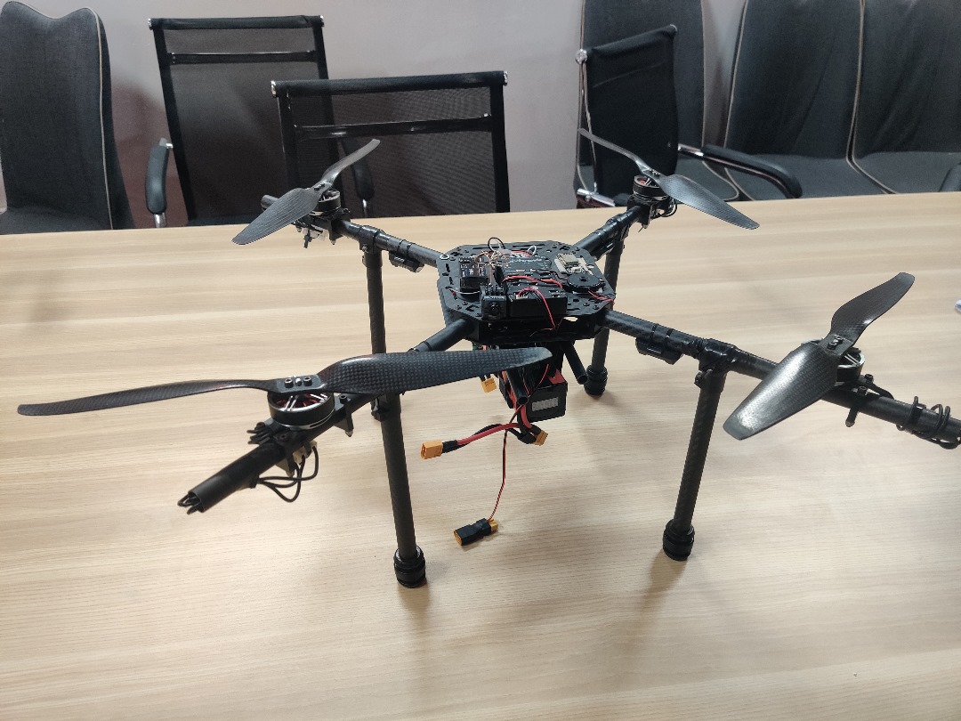
Ikaros V1 Indoor Autonomous Inspection Drone
Circuit Design
The Ikaros V1 featured a well-planned circuit design tailored to support its complex indoor autonomous inspection capabilities. The drone's embedded systems integrated seamlessly with the Pixhawk flight controller and an onboard i7-based computer, ensuring efficient power distribution and data connectivity. Circuit design considerations included stable power regulation for high-current components and reliable sensor interfaces to support real-time data processing and navigation functions.
Control and Navigation Systems
The Ikaros V1 was engineered for fully autonomous indoor inspection, utilizing the Pixhawk flight controller as the primary control unit for maintaining flight stability and executing navigation paths. The i7-based onboard computer handled advanced data processing for real-time decision-making and adaptive navigation. Integrated depth sensors provided precise obstacle detection and avoidance, while the flow sensor added positional accuracy for maintaining steady flight. This combination allowed the drone to navigate complex indoor spaces autonomously and efficiently.
Electrical and Embedded System Design
The electrical system design focused on optimizing power distribution to sustain components like the Pixhawk flight controller and the onboard i7 computer. The design ensured seamless data transfer between the onboard computer and flight controller for coordinated autonomous operations, including stabilization, navigation, and environmental analysis. Power regulation circuits were implemented to maintain the operational integrity of all electronic components during extended inspection missions.
Communication Systems
For robust and efficient data transmission, the Ikaros V1 utilized radio telemetry to establish a reliable communication link between the drone and the control station. This allowed for real-time monitoring and data exchange, enabling operators to receive updates and intervene when necessary. The low-latency communication provided by the radio telemetry ensured that the drone could operate smoothly, with immediate feedback and adaptive control during inspections.
Sensor Integration and Data Acquisition
The Ikaros V1 incorporated a depth sensor for environmental mapping and autonomous navigation, which allowed for effective obstacle detection and avoidance within indoor spaces. The flow sensor contributed to precise positional data, aiding the Pixhawk flight controller in maintaining stable flight. The onboard i7 computer processed sensor data in real time and coordinated with the flight controller for decision-making and path adjustments. This integration enabled the drone to conduct accurate and efficient autonomous indoor inspections with minimal operator intervention.
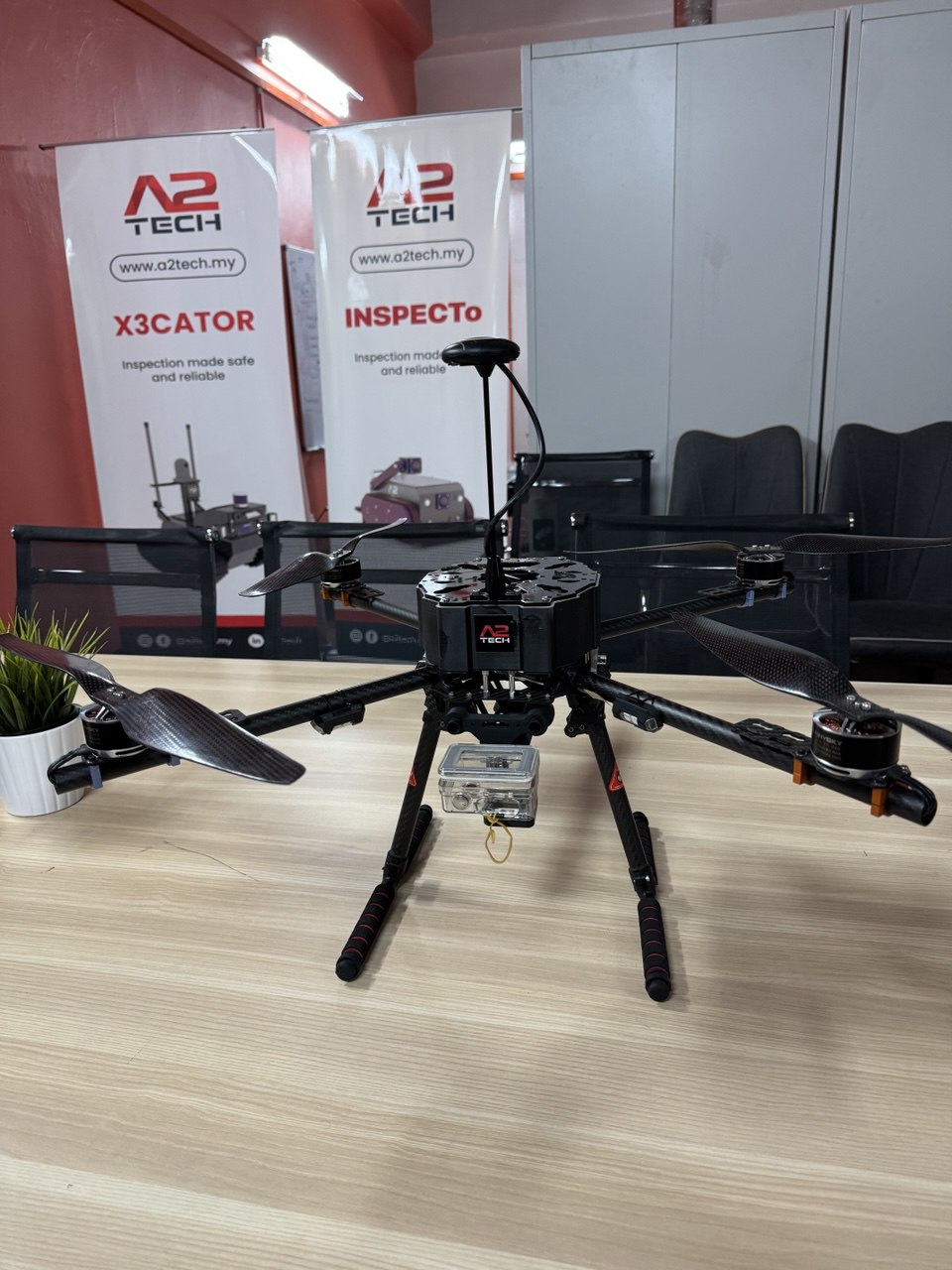
Ikaros V2 Outdoor Inspection, Mapping, and Surveillance Drone

Circuit Design
The Ikaros V2 drone was designed to support outdoor inspection, mapping, and surveillance operations, building on the architecture of its predecessor, Ikaros V1. The circuit design included integration of an i7-based onboard computer and a Pixhawk flight controller, providing seamless connectivity and efficient power distribution. Additional circuit considerations were made to support the integration of a lidar sensor, ensuring that all components could operate reliably in outdoor environments.
Control and Navigation Systems
Similar to Ikaros V1, the Ikaros V2 employed a Pixhawk flight controller for fundamental flight stabilization and path execution, while the i7-based onboard computer managed advanced data processing for real-time mapping, surveillance, and navigation. The addition of a lidar sensor provided enhanced environmental scanning capabilities, enabling precise obstacle detection and terrain mapping. This combination allowed the drone to perform complex navigation tasks, making it ideal for outdoor inspections and surveillance missions.
Electrical and Embedded System Design
The electrical system design was enhanced to accommodate the lidar sensor and outdoor operational requirements. The system ensured efficient power distribution to support the high-power demands of the i7 onboard computer and other components, including the Pixhawk flight controller. The design allowed for seamless data flow and synchronization between the onboard computer and flight controller, supporting real-time data analysis, adaptive navigation, and mapping functions. Power regulation circuits were integrated to maintain stable operations in varying outdoor conditions.
Communication Systems
The Ikaros V2 was equipped with radio telemetry for reliable long-distance communication, facilitating real-time data exchange between the drone and the control station. This setup ensured that operators could monitor the drone's status and receive real-time feedback, essential for outdoor inspection and surveillance operations. The robust communication system provided low-latency transmission, supporting immediate operator adjustments and adaptive control when necessary.
Sensor Integration and Data Acquisition
The Ikaros V2 expanded on its predecessor's capabilities by integrating a lidar sensor, which provided detailed 3D mapping and enhanced obstacle detection for outdoor environments. This, combined with a depth sensor and flow sensor, allowed for accurate environmental mapping and navigation. The i7-based onboard computer processed data from these sensors and worked in coordination with the Pixhawk flight controller to make real-time navigational decisions. This sensor integration enabled the drone to conduct comprehensive inspection, mapping, and surveillance missions with minimal operator input.
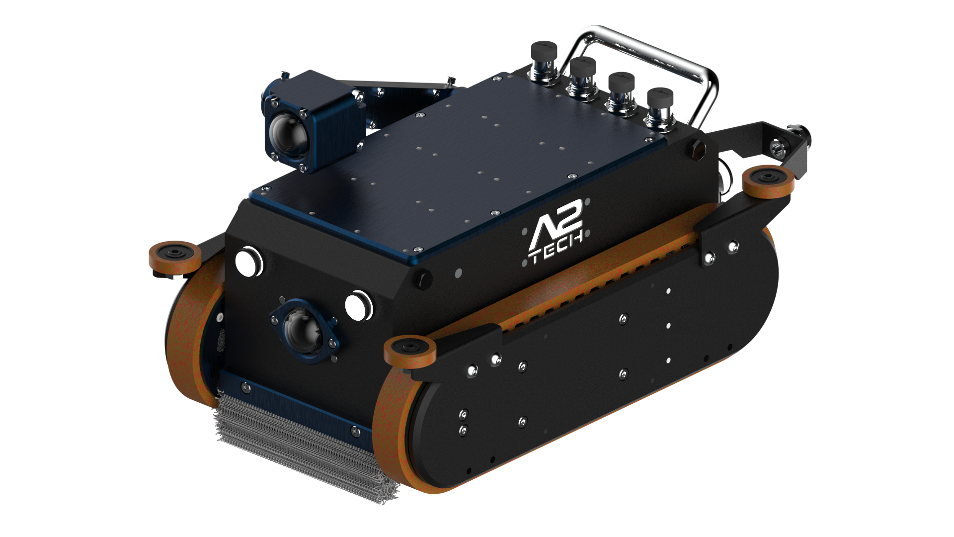
Inspecto-D Multitask Modular Duct Robot
PCB and Circuit Design
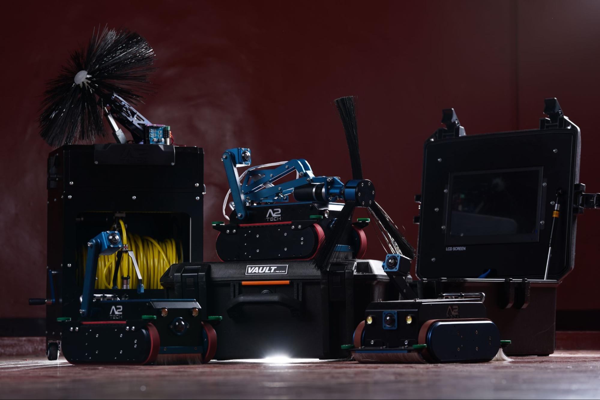
The Inspecto-D robot featured a custom-designed Raspberry Pi HAT as the main control hub, including an integrated USB hub, motor driver circuits, actuator control, lidar support, CANBUS communication, and connections for a laser profiler. The PCB design also supported powerline communication for reliable data transmission to the control box, ensuring stable operation in confined duct environments.
Control and Navigation Systems
Powered by a Raspberry Pi, the control system managed motor actuation for movement within ducts and pipelines. The custom PCB facilitated motor control and lidar integration for autonomous navigation and spatial data collection. A PTZ module provided inspection capabilities without influencing navigation.
Electrical and Embedded System Design
The electrical design supported multitasking through the Raspberry Pi HAT, integrating motor drivers and powerline communication for data transfer. Power management ensured stable operations under load, while CANBUS enabled efficient subsystem data exchange.
Communication Systems
Using a powerline communication module, Inspecto-D allowed high-bandwidth data and video transmission to the control box. This setup provided real-time feedback, essential for precise inspection and cleaning tasks.
Sensor Integration and Data Acquisition
Inspecto-D was equipped with lidar, a laser profiler, and three cameras (including a PTZ module) for detailed profiling, mapping, and inspection. The Raspberry Pi processed sensor data and communicated with the control box in real time, aiding informed operator decisions.
Certification
Certified under IEC 62368-2018 by SIRIM QAS, ensuring safety and performance standards suitable for industrial use in confined spaces.
Oil2Wang Bio-Diesel Collection Booth


PCB and Circuit Design
Designed a custom PCB with user authentication, oil measurement, and data communication features. The circuit integrated an oil density sensor to validate used cooking oil, optimizing collection reliability.
Control and Navigation Systems
The autonomous control unit managed user interaction, oil intake, and transaction processing. Algorithms ensured accurate oil volume measurement and secure transactions.
Electrical and Embedded System Design
Real-time processing handled oil level and density inputs, with solar power management ensuring consistent operation in varying conditions.
Communication Systems
Utilized IoT for data transmission to a central server, enabling transaction monitoring and remote updates, essential for managing multiple booths.
Sensor Integration and Data Acquisition
Included oil density and level sensors to ensure the collection of genuine used oil, with real-time data facilitating immediate transactions and system optimization.
Impact and Recognition
Received multiple awards for environmental innovation, including the Gold Award and Special Community Award at the INATEX and Japan Intellectual Property Association's Special Award for Environmental Innovation.
Autonomous vehicles control and navigation board powered by ARM® Cortex®-M7 processor with RC, CANBUS, RS232 and RS485 support
MultiDrive UGV Control Board
Description
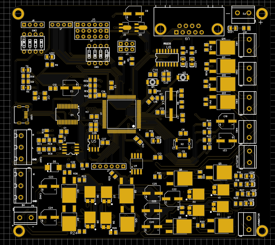
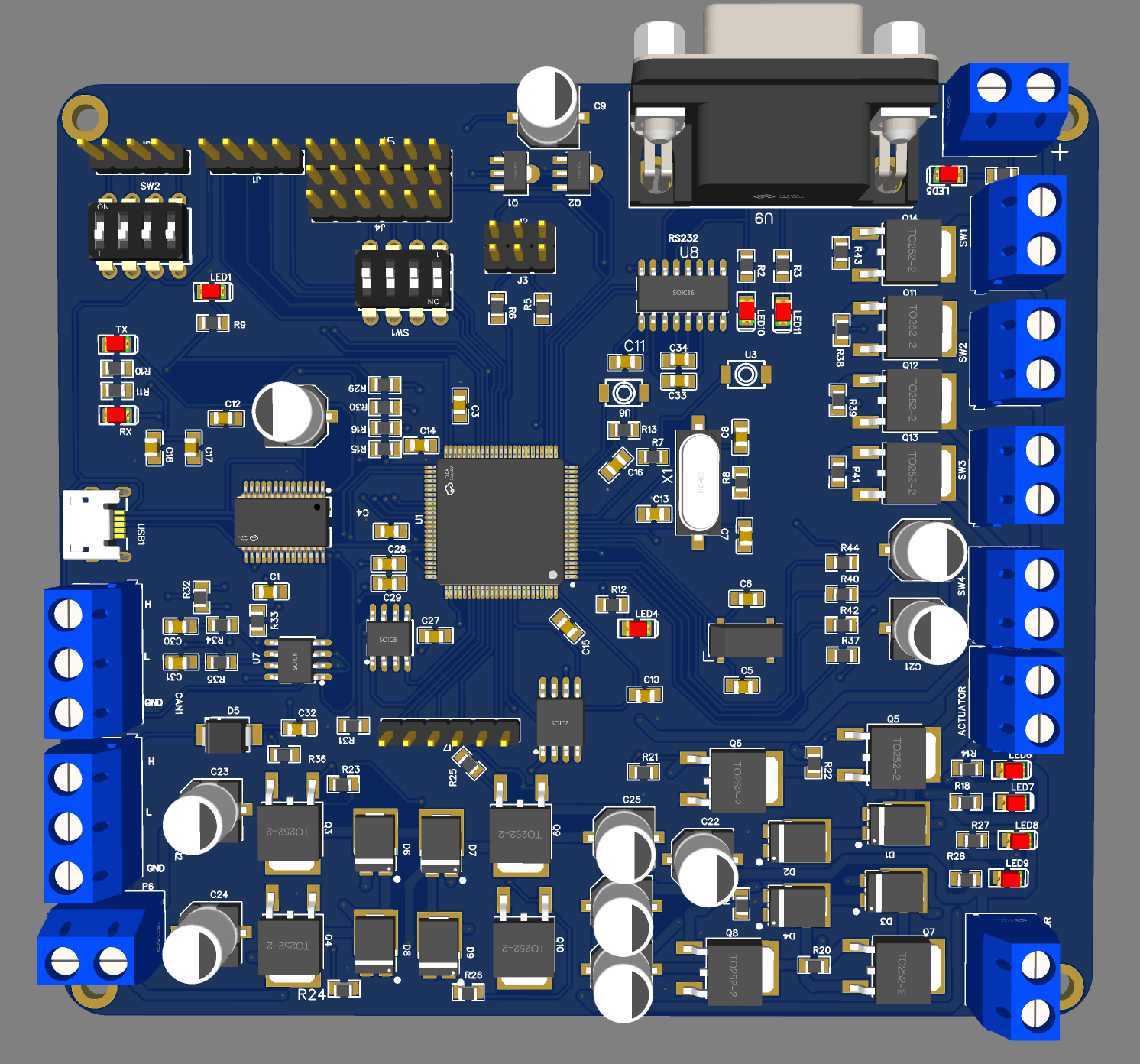
This custom-designed control and navigation board is built to power autonomous Unmanned Ground Vehicles (UGVs), utilizing the STM32H743 ARM® Cortex®-M7 processor for high-speed processing and real-time control. The board integrates advanced communication interfaces, high-efficiency power management systems, and comprehensive safety mechanisms, making it ideal for demanding applications in autonomous navigation and multi-functional UGV operations. Each component is meticulously designed to handle intensive workloads, enabling precision, adaptability, and resilience in dynamic environments.
Specifications
- High-Performance STM32H743 ARM® Cortex®-M7 Processor: At the core of the board is the STM32H743 microcontroller, featuring the ARM® Cortex®-M7 architecture, clocked up to 480 MHz. This powerful processor is optimized for real-time applications, delivering unparalleled processing speeds essential for complex navigation algorithms and multi-threaded control tasks. The Cortex®-M7 architecture includes advanced floating-point unit (FPU) support, enabling precise mathematical computations, critical for robotics applications that require rapid, accurate processing of sensor data and control commands.
- Multi-Protocol Communication Interface:
- CANBUS: The onboard CANBUS interface supports high-speed, fault-tolerant data communication, ideal for reliable control and monitoring in automotive and robotic applications. CANBUS enables real-time data exchange between modules, ensuring synchronized operations and system stability.
- RS232: Featuring an RS232 interface, the board can easily connect to serial devices, sensors, and controllers, making it compatible with a wide range of legacy and modern devices. RS232 provides stable communication over short distances, ideal for close-proximity data exchange.
- RS485: The RS485 interface supports long-distance, differential signaling, enabling the board to communicate over extended distances without signal degradation. This feature is critical for large-scale or distributed UGV systems that require robust, interference-resistant data transmission.
- RC (Remote Control): The RC interface allows remote operation, offering manual control for initial setup, calibration, or emergency override. This interface is crucial for systems that need adaptable control options, providing a seamless transition between autonomous and manual modes.
- High-Speed MOSFET-Based Power Switching:The board incorporates a high-speed MOSFET-based switching circuit for power management. This MOSFET switch ensures rapid switching with low on-resistance, providing efficient power delivery to high-current loads. The design minimizes power dissipation, reducing heat generation and enhancing overall efficiency, essential for sustaining performance in energy-intensive UGV applications
- Advanced Emergency Kill System: An emergency kill system is integrated to provide immediate system shutdown in the event of collision, fault, or safety-critical situations. This system is engineered with a rapid-response circuit that can cut power to all major systems instantaneously, safeguarding the UGV, its surroundings, and any personnel involved. The kill switch is manually or automatically activated, ensuring versatile control over safety operations.
- Dual High-Power Motor Driver Circuits: Two high-power motor driver circuits are embedded on the board, providing independent control over motor speed, direction, and torque. Each driver circuit is optimized for high-current operations and equipped with protections against overcurrent and overheating. These drivers can support complex mechanical attachments, such as robotic arms, and allow for precise control over motor-driven components, crucial for tasks that require multi-axis movements or adaptive motor control.
- Modular Design for Attachments and Expansion: Designed with modularity in mind, the board supports easy attachment of additional modules and components, allowing users to expand its functionality based on specific mission requirements. The modular design enables swift integration of various sensors, actuators, and communication modules, making it adaptable to a range of UGV configurations. This feature is especially valuable in dynamic operational settings where versatility and customization are key.
- Real-Time Processing for Navigation and Control: Leveraging the ARM® Cortex®-M7’s real-time processing capabilities, the board is optimized for executing complex control algorithms with minimal latency. The processor’s low interrupt latency and deterministic response times make it highly suitable for autonomous navigation, where immediate feedback from sensors and fast execution of control commands are critical. This capability enhances the UGV’s ability to adapt to environmental changes in real-time, enabling safe and efficient autonomous operation.
- Power-Efficient Voltage Regulation: The board includes an advanced voltage regulation system that stabilizes power across all components, accommodating input fluctuations and ensuring consistent operation under varying power loads. This regulation is critical for maintaining performance stability, especially in environments with inconsistent power sources or under heavy workloads.
- Robust Build Quality and Durability: All components on this board are selected for their high durability and resilience, making it well-suited for harsh operational environments. This includes industrial-grade connectors, enhanced PCB thickness for thermal management, and reinforced soldering points. The design is tested to withstand shock, vibration, and extreme temperatures, ensuring dependable performance in rugged applications.
Key Benefits
This MultiDrive UGV Control Board offers robust processing power, advanced communication interfaces, and superior safety features, making it the ideal solution for demanding autonomous vehicle applications. Whether for complex autonomous navigation, multi-functional UGV operations, or integration with additional sensors and modules, this board provides the flexibility and reliability required for success in challenging environments.
ARM® Cortex®-M7 based Microcontroller (STM32H743)
Description
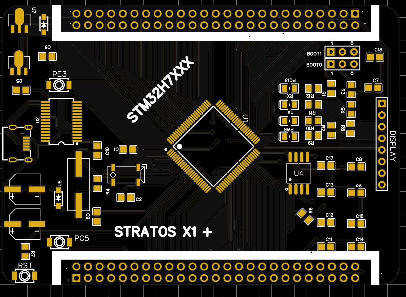
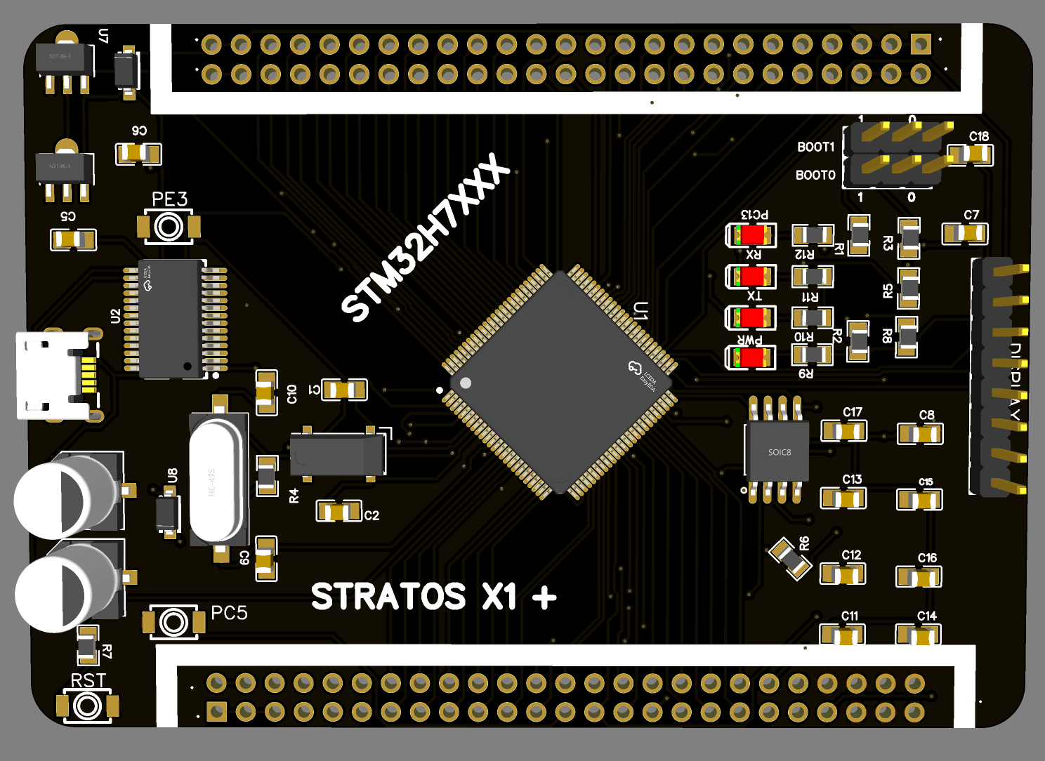
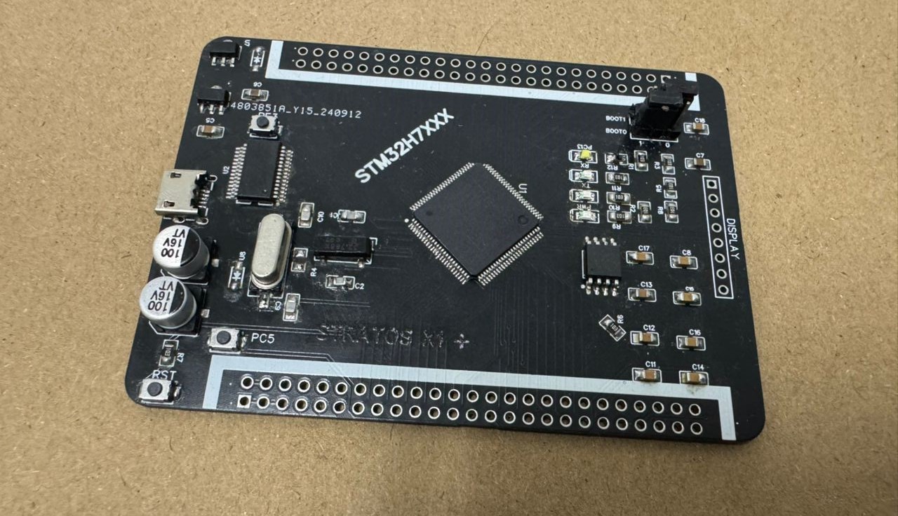
This custom-designed microcontroller board, built around the powerful STM32H743VIT6, is designed to deliver high-performance computing capabilities for advanced embedded applications. Featuring an integrated FTDI module, this board offers plug-and-play compatibility with the Arduino IDE, simplifying programming and debugging. With onboard storage options and advanced computational capabilities, this board is an excellent solution for data-intensive applications requiring real-time processing, AI, and DSP support.
Key Features and Technical Specifications
- High-Performance STM32H743VIT6 ARM® Cortex®-M7 Processor: The STM32H743VIT6 microcontroller at the heart of this board features an ARM® Cortex®-M7 processor, clocked at up to 480 MHz, providing exceptional computing power for demanding applications. The Cortex®-M7 core is equipped with a Floating Point Unit (FPU) and DSP instructions, making it highly suitable for advanced tasks such as machine learning inference, digital signal processing (DSP), and control algorithms for real-time data analysis and processing.
- AI and Machine Learning: With built-in support for Edge AI and machine learning, the processor can run neural network inference models, making it ideal for applications in object detection, pattern recognition, and sensor fusion directly on the microcontroller, without needing additional processing hardware.
- Digital Signal Processing (DSP): The ARM Cortex-M7 includes DSP extensions and an FPU, allowing it to perform complex signal processing tasks, such as audio and image processing, data filtering, and frequency analysis. This feature makes the board an excellent choice for applications that require real-time signal manipulation.
- Integrated FTDI Module for Arduino Compatibility: The FTDI module offers seamless plug-and-play functionality, allowing the board to be used directly with the Arduino IDE, enabling quick and convenient programming and debugging. This feature is especially useful for rapid prototyping and for developers familiar with the Arduino ecosystem.
- Versatile Data Storage Options:
- SD Card Slot: Integrated SD card support allows high-capacity storage for data logging, ideal for applications with intensive data requirements. The SD card can also operate in SPI mode, offering a secondary flash storage option for additional flexibility.
- External SPI Flash: Additional external SPI flash provides rapid data access, enhancing the board’s storage capability for data-intensive applications such as machine learning model storage or environmental data logging.
- Enhanced SPI Communication: The board supports multiple SPI interfaces, allowing concurrent access to the SD card, external SPI flash, and other peripherals. This multi-SPI configuration enables high-speed data transfer essential for applications requiring large-scale data handling and real-time data processing.
- Comprehensive I/O and Peripheral Support: Equipped with extensive I/O and peripheral options, this board is designed to support complex embedded applications:
- Digital and Analog I/O: A variety of digital and analog I/O pins support flexible input/output configurations for connecting to sensors, actuators, and other components.
- GPIO Expansion: General-purpose I/O pins allow for easy expansion and custom configurations, ideal for bespoke applications requiring additional peripherals.
- UART, I2C, and CAN Interfaces: Standard UART, I2C, and CAN interfaces offer versatile communication options, supporting simultaneous communication with multiple devices.
- Real-Time Performance for AI, DSP, and Control Applications: The ARM® Cortex®-M7’s real-time processing capabilities make this board suitable for AI, DSP, and control-based applications that require low-latency, high-precision operations. With hardware-accelerated FPU and DSP extensions, the board can handle real-time machine learning inference, signal processing, and other complex computational tasks without sacrificing performance.
- Efficient Power Management: Designed with a reliable power regulation system, the board ensures stable operation under varied power conditions, optimizing energy consumption and making it suitable for portable and battery-powered applications.
- Compact and Durable Design: This compact board fits well in embedded systems and is constructed with high-quality components to ensure long-lasting performance, even in rugged conditions. Its form factor and durability make it suitable for both rapid prototyping and deployment in field applications.
Key Benefits
This STM32H743VIT6-based microcontroller board combines robust computational power, versatile storage options, and Arduino-compatible programming, offering a comprehensive solution for developers working on cutting-edge embedded applications requiring AI, DSP, and real-time data processing capabilities.
ARM® Cortex®-M4 based Microcontroller (STM32F407)
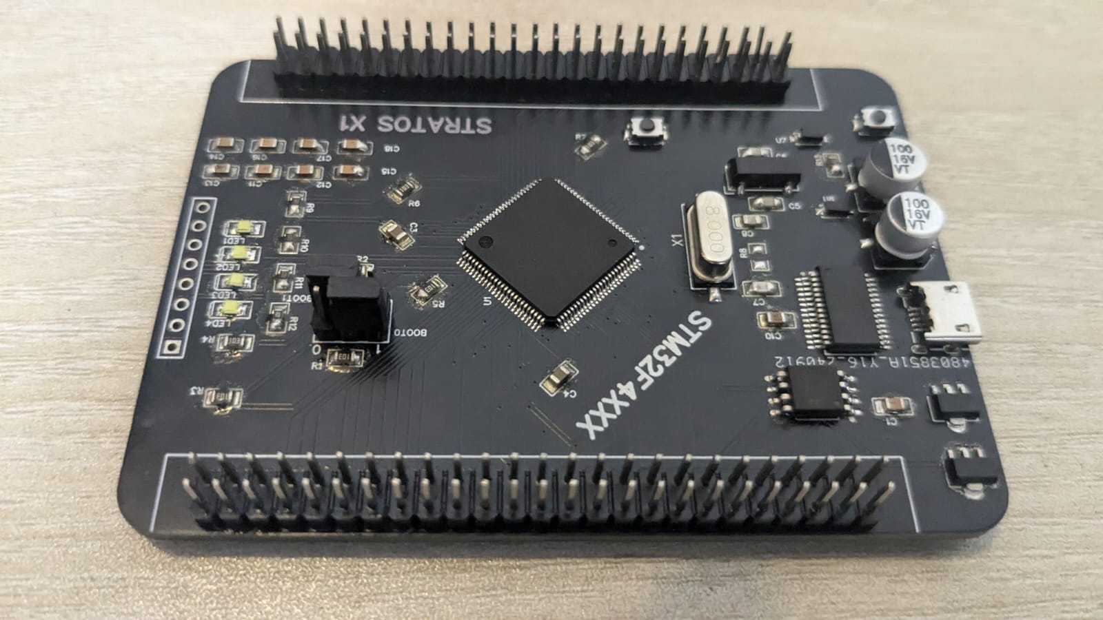
Description
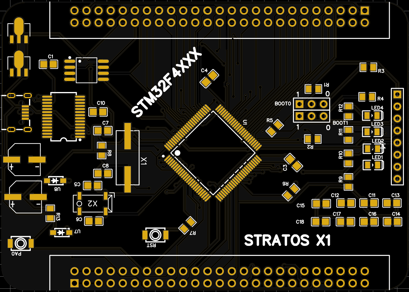
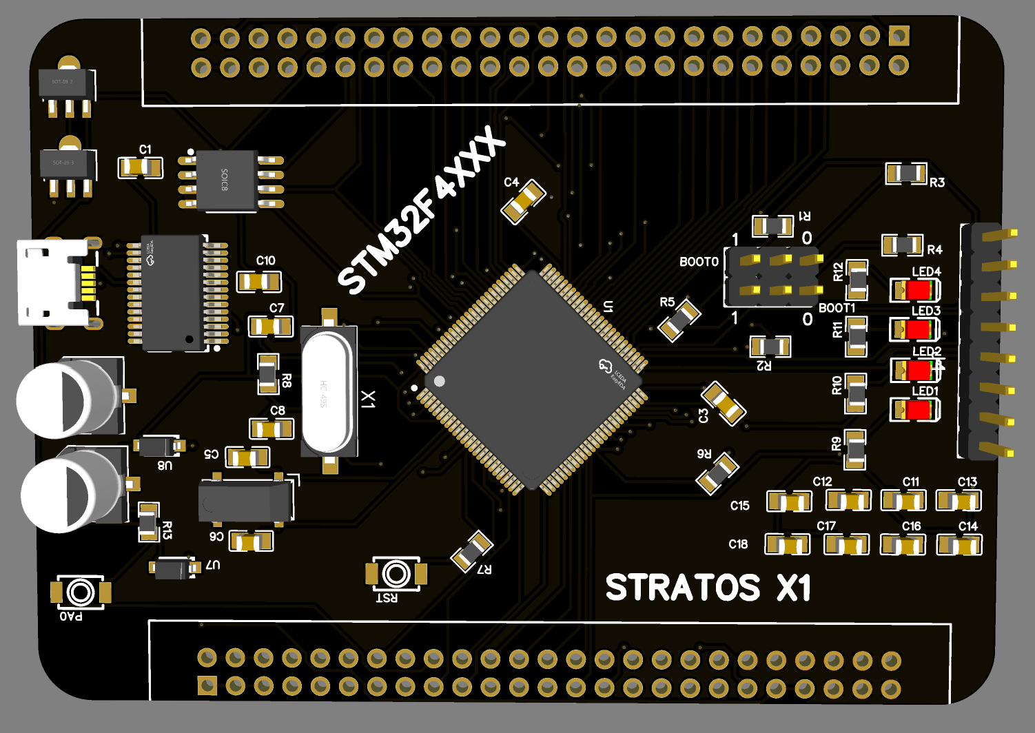
This custom-designed microcontroller board, based on the STM32F407VGT6, is engineered to provide high-performance computing for embedded applications. Featuring an integrated FTDI module, this board supports plug-and-play functionality with the Arduino IDE, simplifying development and debugging. With advanced data storage options and robust real-time processing capabilities, this board is well-suited for data-intensive and real-time applications requiring reliable performance in compact embedded systems.
Key Features and Technical Specifications
- High-Performance STM32F407VGT6 ARM® Cortex®-M4 Processor: The STM32F407VGT6 microcontroller features an ARM® Cortex®-M4 core running at up to 168 MHz. Optimized for efficient real-time processing, the Cortex-M4 core includes a Floating Point Unit (FPU) and DSP instructions, allowing it to handle digital signal processing (DSP) tasks and AI model inference, making it suitable for applications requiring complex algorithms and precise control.
- Digital Signal Processing (DSP): The ARM Cortex-M4 architecture includes DSP extensions and FPU support, enabling the microcontroller to handle tasks such as data filtering, frequency analysis, and other signal processing requirements essential for real-time applications.
- AI and Machine Learning: While optimized for DSP, the STM32F407VGT6 can also support basic machine learning models, enabling applications such as pattern recognition and simple sensor-based AI processing.
- Integrated FTDI Module for Arduino Compatibility: The board’s FTDI module allows for easy plug-and-play functionality with the Arduino IDE, enabling straightforward programming and debugging. This integration simplifies the development process, particularly for users accustomed to the Arduino environment.
- Versatile Data Storage Options:
- SD Card Slot: An SD card slot provides extensive storage capacity, making it suitable for applications requiring frequent data logging. The SD card can also be configured to function as an SPI flash, offering flexibility for additional storage needs.
- External SPI Flash: With external SPI flash storage, the board supports rapid data retrieval and storage for configuration files, log data, and other critical information needed for embedded applications.
- Enhanced SPI Communication: The board features multiple SPI interfaces, enabling efficient management of data transfer between the SD card, external SPI flash, and other peripherals. This multi-SPI setup is ideal for applications that require simultaneous access to storage and sensor data, ensuring minimal latency.
- Comprehensive I/O and Peripheral Support: To support a variety of embedded applications, this board includes flexible I/O options:
- Digital and Analog I/O: A range of digital and analog I/O pins provide customizable input/output configurations, making it easy to connect to sensors, actuators, and other components.
- GPIO Expansion: Multiple GPIO pins allow for peripheral expansion, supporting custom configurations for complex applications.
- UART, I2C, and CAN Interfaces: Built-in UART, I2C, and CAN interfaces enable communication with a wide range of modules, allowing for versatile data exchange and device compatibility.
- Real-Time Performance for DSP and Control Applications: The ARM® Cortex®-M4’s real-time processing capabilities make this board highly suitable for applications requiring low-latency, high-precision operations. Its DSP instructions and FPU enable real-time signal processing and control, ideal for tasks such as sensor data interpretation, motor control, and environmental monitoring.
- Reliable Power Management: With an efficient power regulation system, the board ensures stable performance under varied power conditions. This feature is essential for battery-powered applications and embedded systems that operate in fluctuating environments.
- Compact and Durable Design: The board’s compact form factor and durable construction make it suitable for integration into a wide range of embedded systems. Its robust design ensures reliable performance, even in rugged conditions, making it ideal for both prototyping and deployment.
Key Benefits
This STM32F407VGT6-based microcontroller board offers a balanced mix of performance, flexibility, and ease of use, making it an excellent choice for embedded developers working on applications requiring DSP, real-time processing, and data logging capabilities.
ARM® Cortex®-M3 based Microcontroller (STM32F103)
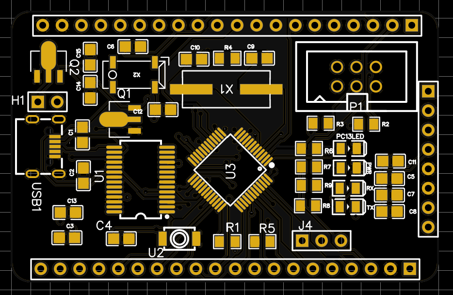
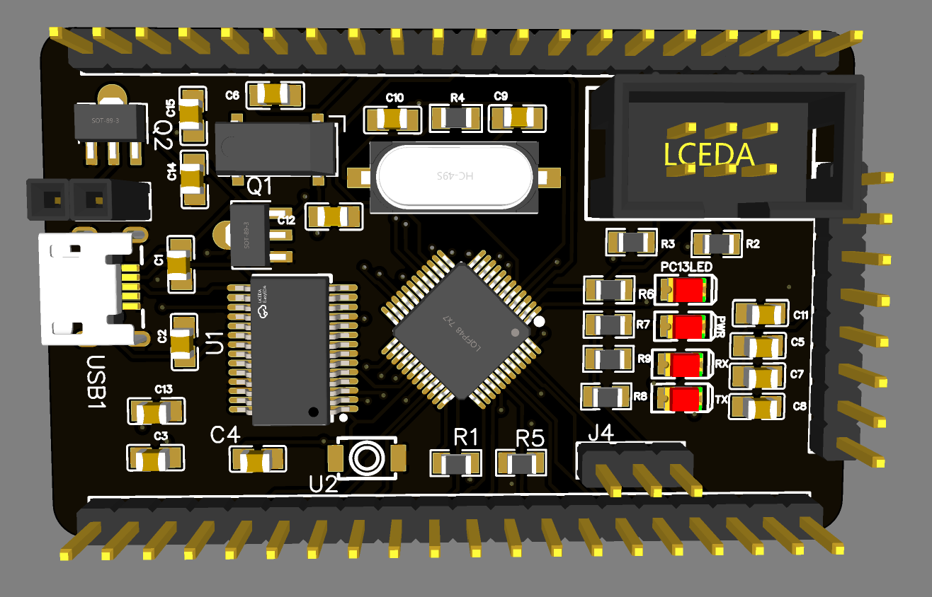
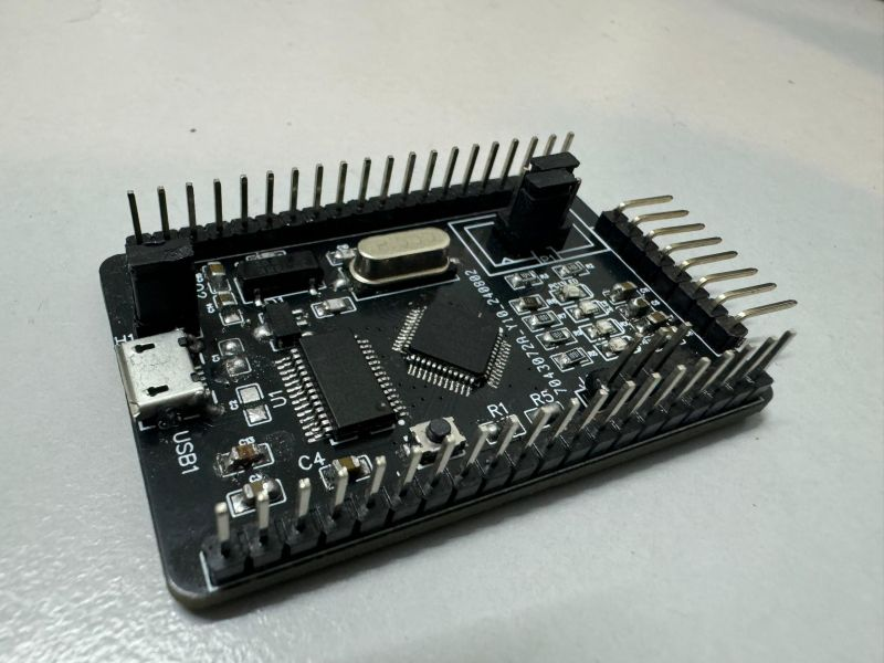
Description
This STM32F103CBT6-based microcontroller is designed as a compact and efficient solution for basic embedded applications. Equipped with an integrated FTDI module, it provides easy plug-and-play support for the Arduino IDE, allowing for simplified programming and debugging. While designed with essential functionality, this board maintains robust performance and versatility for a range of foundational projects and prototyping needs.
Key Features and Technical Specifications
- STM32F103CBT6 ARM® Cortex®-M3 Processor: At the core of this board is the STM32F103CBT6 microcontroller, based on the ARM® Cortex®-M3 architecture, running at up to 72 MHz. Known for its reliability and power efficiency, the Cortex-M3 processor delivers enough performance for fundamental tasks, sensor interfacing, and control applications. It’s ideal for developers needing a straightforward and low-power microcontroller.
- Integrated FTDI Module for Arduino IDE Compatibility: Featuring an FTDI module, this board allows for seamless plug-and-play compatibility with the Arduino IDE. This integration enables easy programming and debugging through USB without the need for external adapters, making it suitable for quick prototyping and development by users familiar with the Arduino platform.
- Essential I/O and Peripheral Support: This board is equipped with essential input/output options, supporting fundamental embedded applications:
- Digital and Analog I/O: A balanced set of digital and analog I/O pins provides flexibility for basic sensor and actuator interfacing, ideal for educational and entry-level projects.
- GPIO Expansion: Multiple General-Purpose Input/Output (GPIO) pins allow for additional peripheral connections, enabling customization and expansion as needed.
- UART, I2C, and SPI Interfaces: The board supports essential communication protocols such as UART, I2C, and SPI, facilitating connectivity with a variety of sensors, displays, and other peripheral devices.
- Compact and Power-Efficient Design: Built with simplicity in mind, this board’s compact form factor makes it suitable for minimalistic projects and embedded systems with space constraints. Its power-efficient design allows it to operate on minimal energy, making it ideal for low-power applications and battery-operated devices.
Key Benefits
This STM32F103CBT6-based microcontroller offers an accessible, easy-to-use platform for basic embedded development. Its simplicity, combined with Arduino IDE compatibility, makes it an excellent choice for educators, students, and engineers looking for a straightforward solution for foundational projects.
Control and Modular Function Board for Inspecto-D
Description
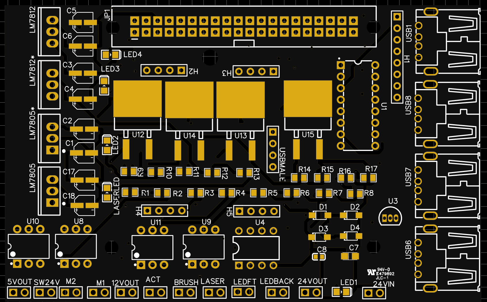
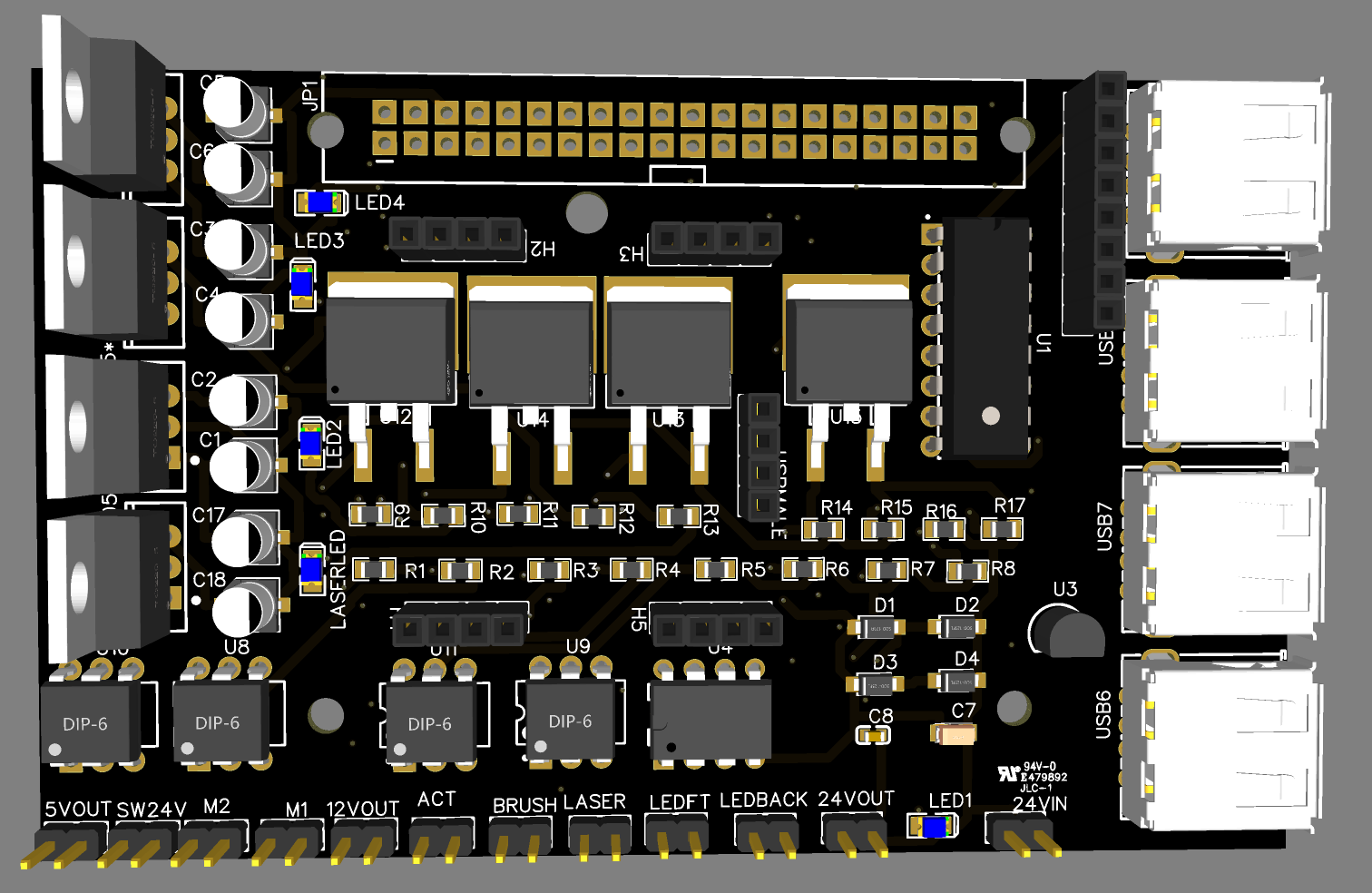
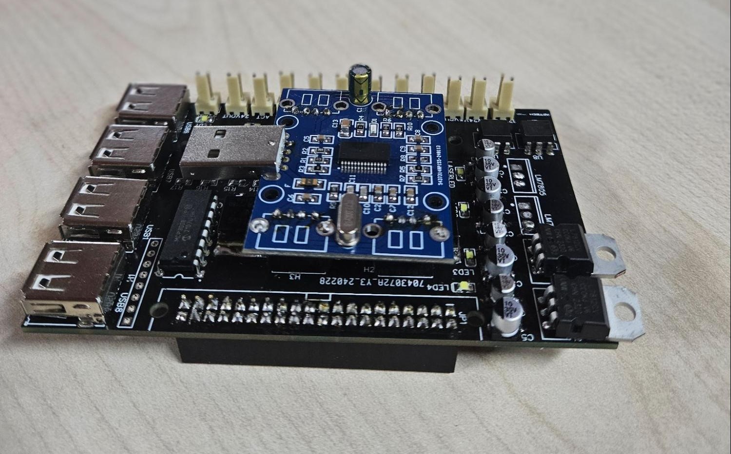
This custom-designed Raspberry Pi HAT for the Inspecto-D robot serves as an integrated control and power distribution solution, optimized for the unique requirements of duct cleaning, inspection, mapping, and laser profiling. Its feature-rich design enables efficient management of critical robotic components, making it ideal for high-precision and high-reliability applications. The board is certified to IEC 62368-2018 standards, ensuring compliance with stringent safety and performance criteria, as confirmed by SIRIM QAS International Sdn. Bhd.
Key Features and Specifications
- Motor Control and Actuator Management: Equipped with an H-bridge circuit utilizing N-type MOSFETs, the board provides reliable and precise control of the robot's motor, brush motor, and actuator. This robust design enables consistent operation even under demanding conditions.
- LED Intensity Control and Additional Functions: A dedicated MOSFET-based switch allows for adjustable LED intensity, supporting variable lighting conditions for inspections. This switch can be adapted for other functions as well, offering flexibility and user-defined control.
- USB Hub with 4 Downstream Ports: The integrated USB hub supports four downstream ports, enabling connectivity with multiple peripherals. This feature enhances the robot's expandability, allowing additional sensors or USB-compatible modules to be added as needed.
- Versatile Power Regulation: The board includes a voltage regulator tailored for various robotic applications, ensuring consistent power distribution across components. This regulation is crucial for stable performance in environments with fluctuating power demands.
- High-Quality Data Transfer: Designed for high-performance data management, the board can transfer LiDAR data and camera feed directly to the Raspberry Pi. This enables real-time data processing, facilitating accurate mapping and profiling.
- Sensor Integration with Temperature Monitoring: A temperature sensor embedded within the board provides thermal monitoring, enhancing the safety and reliability of the system by preventing overheating. Additionally, the board's ADC allows for analog sensor support, broadening the scope of compatible sensors for environmental data collection.
- Analog-to-Digital Conversion (ADC) Support: The inclusion of an ADC broadens the robot’s sensory capabilities, allowing it to process data from various analog sensors. This versatility enhances the robot's adaptability in environments where specific sensory inputs are critical.
High-Power DC Motor Driver
Description
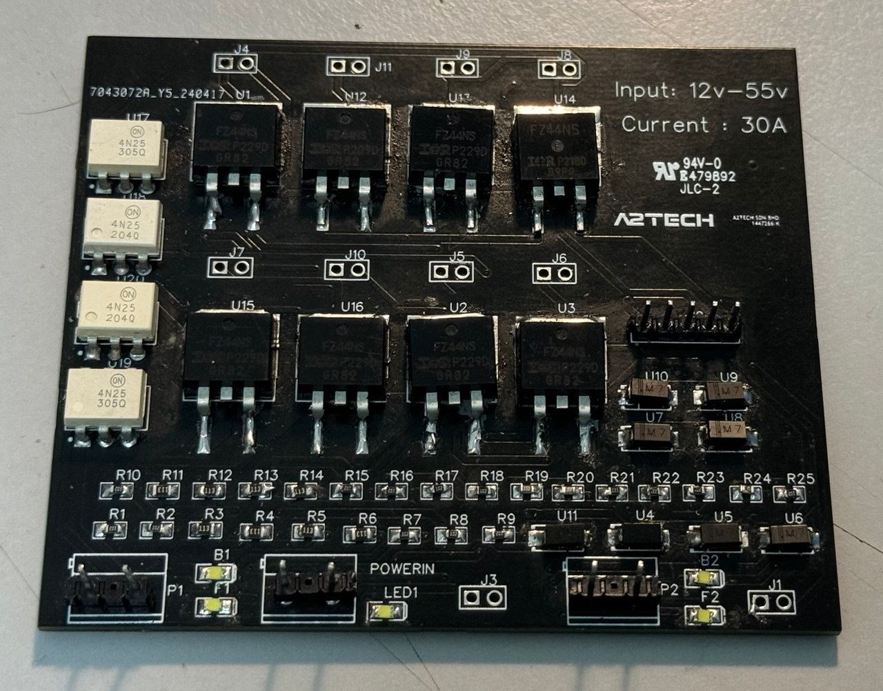
This project focuses on the design and implementation of a high-power motor driver circuit capable of controlling motors with a wide input voltage range of 12V to 55V and a maximum current capacity of 30A. The circuit utilizes IRFZ44N MOSFETs for efficient power switching, paired with opto-couplers for electrical isolation, ensuring the safety of the low-voltage control electronics. This design is ideal for high-power applications in robotics, electric vehicles, industrial machinery, and automation systems, where reliable motor control and protection from electrical transients are essential.
Key Features
- High Power Handling: The circuit supports an input voltage range of 12V to 55V and is capable of driving motors with a maximum current of 30A, making it suitable for high-power applications in robotics, automation, and industrial machinery.
- IRFZ44N MOSFETs for Efficient Switching: The use of IRFZ44N MOSFETs ensures low on-resistance (Rds(on)), enabling efficient power switching and minimizing heat generation. These MOSFETs handle high current loads reliably while providing fast switching times, essential for high-performance motor control.
- Opto-Coupler for Electrical Isolation: Opto-couplers are used to provide electrical isolation between the low-voltage control circuit and the high-power motor drive circuitry. This enhances safety by protecting sensitive components from voltage spikes and electrical noise that may occur in the power section.
- Thermal and Overcurrent Protection: The circuit design incorporates thermal management features to prevent overheating during extended high-current operation. In addition, current-limiting protections are built in to safeguard both the driver and the motor from overcurrent conditions, ensuring reliability under heavy load.
- Wide Range of Applications: Ideal for controlling DC motors, this driver is highly adaptable for applications in robotics, electric vehicles, automated systems, and other industrial uses where high power and precision are required.
- Simple Interface for Easy Integration: The circuit is designed with compatibility in mind, offering an easy interface for control through microcontrollers such as Arduino and STM32. This makes integration with various control systems straightforward and efficient.
Technical Specifications
- Input Voltage Range: 12V to 55V
- Maximum Output Current: 30A
- MOSFET Type: IRFZ44N (N-channel MOSFET)
- Opto-Coupler: For electrical isolation between control and power sections
- Switching Frequency: Dependent on the specific design and load requirements
- Protection Features: Overcurrent and thermal protection, current-limiting circuitry
- Control Interface: Compatible with microcontrollers (e.g., Arduino, STM32)
- Applications: Robotics, electric vehicles, industrial machinery, automation systems
Raspberry Pi Relay HAT Module
Description
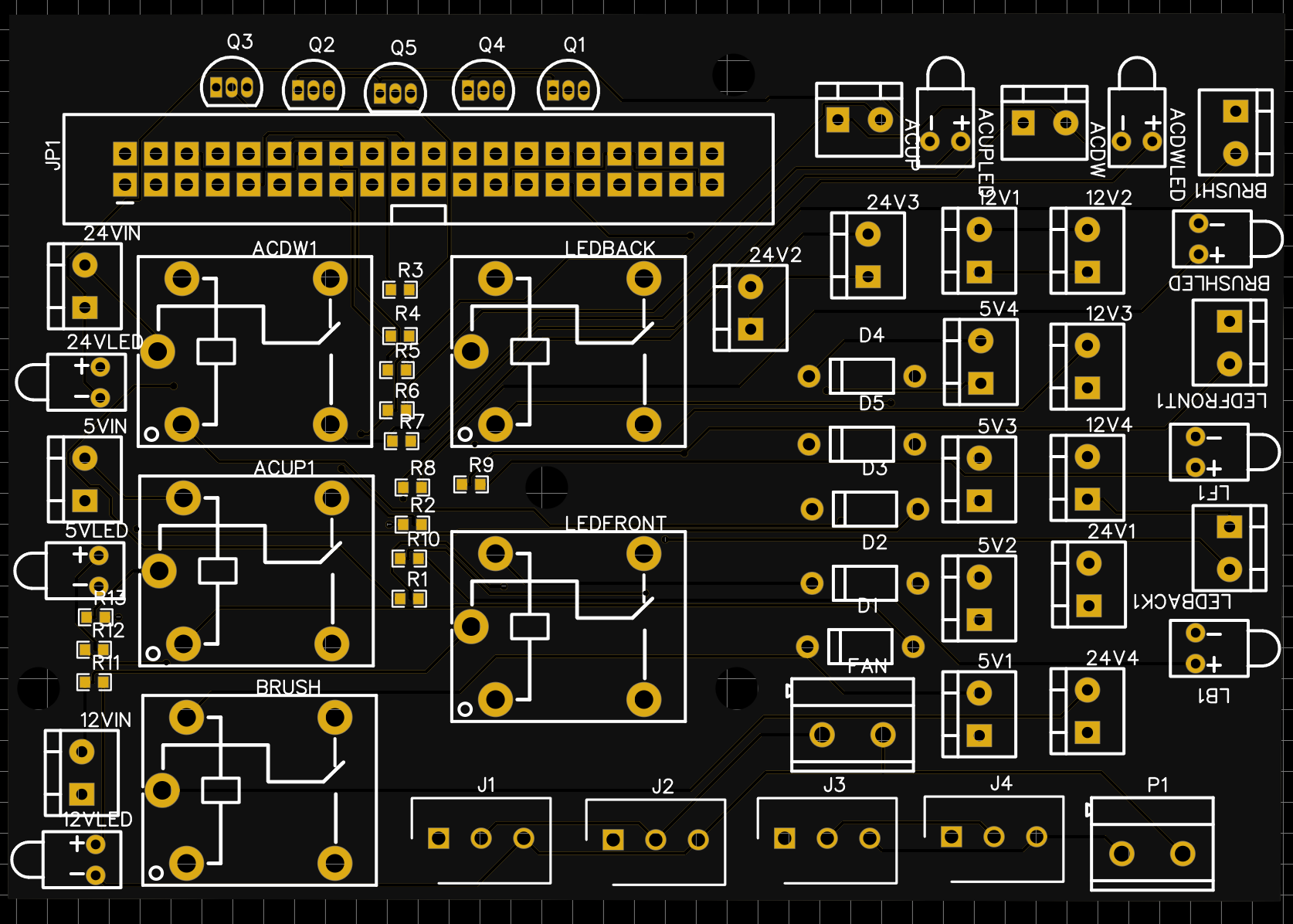
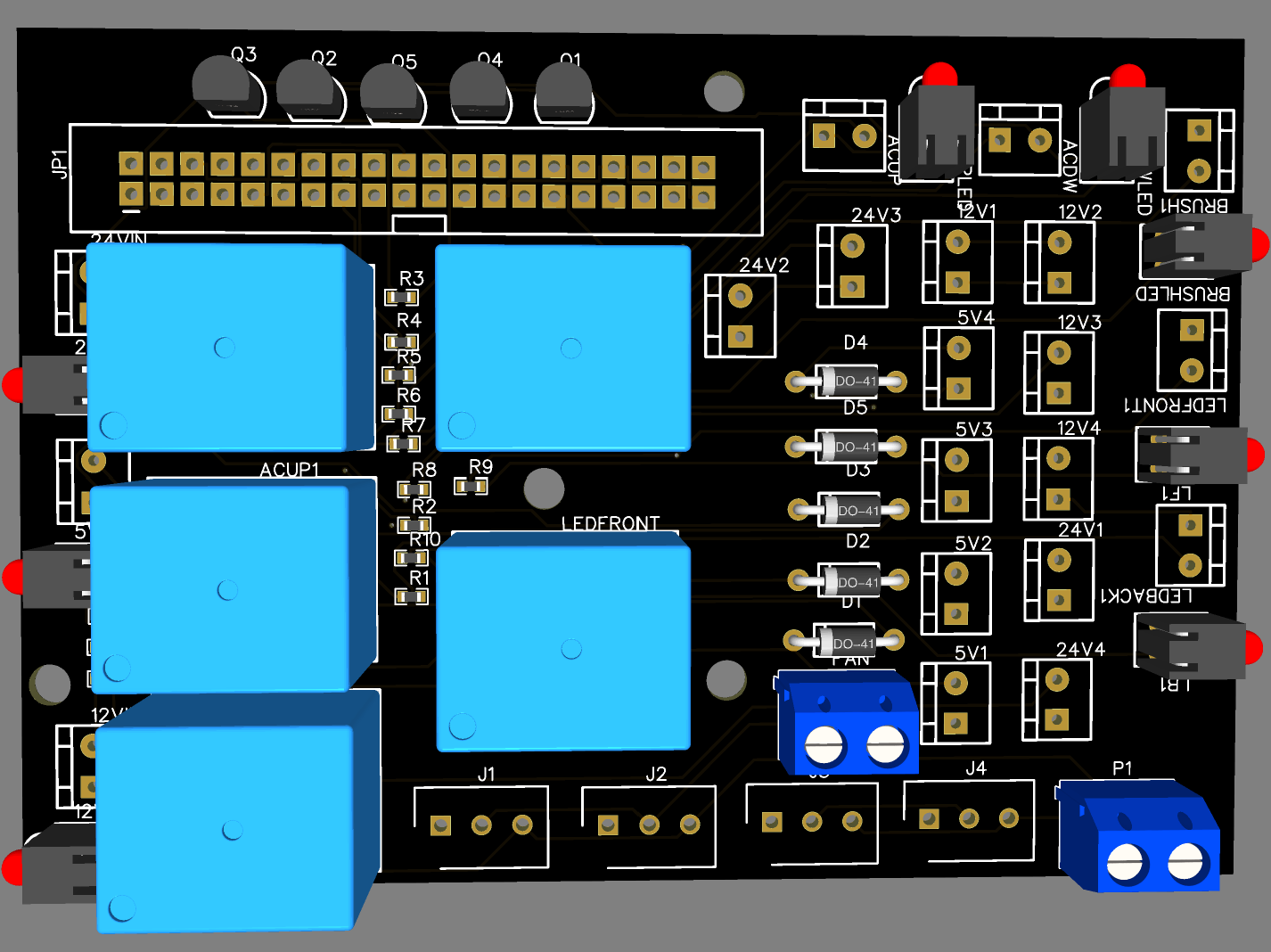
The Raspberry Pi Relay HAT is designed to provide reliable power control and high-frequency switching for IoT and automation applications. Equipped with SRD-05VDC-SL-C relays, it allows control of high-power devices with ease. This HAT is perfect for home automation, industrial control, or any project that requires robust switching capabilities, offering seamless integration with your Raspberry Pi setup.
Key Features & Specifications
- Relay Type: SRD-05VDC-SL-C, known for stable and reliable performance.
- Switching Capacity: Supports up to 10A at 250VAC or 30VDC per relay.
- Control Voltage: 5V DC, compatible with Raspberry Pi and other 5V microcontroller systems.
- GPIO Compatibility: Direct control via Raspberry Pi GPIO pins, allowing for easy integration.
- Low-Voltage Trigger: Operates with 5V logic levels for efficient control.
- Multiple Relays: Available with 4 relays (configurations may vary).
- Compact Design: Space-efficient and easy to install on Raspberry Pi boards without the need for additional components.
- Overcurrent Protection: Built-in protection to prevent damage from overloads.
- Operating Temperature: Suitable for use in harsh environments with a range of -40°C to +85°C.
CH340G USB to UART Module
Description
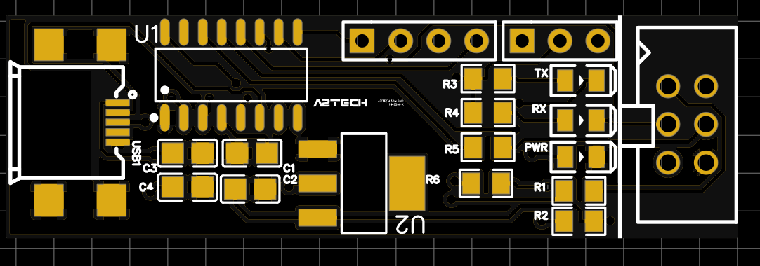
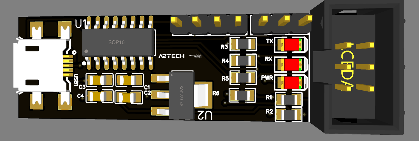
The CH340G USB to UART module is a reliable and cost-effective solution for converting USB signals to UART (serial) communication. Based on the popular CH340G chip, this module is perfect for applications where USB-to-serial communication is needed, such as with microcontrollers, sensors, and peripheral devices. The module is plug-and-play and offers a simple way to interface USB-based systems with serial devices, supporting a wide range of baud rates and offering stable communication.
Key Features & Specifications
- CH340G Chip: Utilizes the robust and widely supported CH340G chip for reliable USB-to-UART communication.
- USB Interface: Provides easy USB connection for microcontrollers, sensors, and other devices that support UART.
- Wide Baud Rate Support: Supports a wide range of baud rates (up to 1 Mbps or higher), making it suitable for various communication needs.
- Operating Voltage: 5V or 3.3V (depending on configuration).
- Data Pins: Includes standard TX (Transmit) and RX (Receive) pins for UART communication.
- Plug-and-Play: No drivers required on most operating systems, including Windows, Linux, and macOS.
- Compact Design: Small, space-efficient form factor, ideal for embedded systems and prototyping.
- Overcurrent Protection: Built-in protection to ensure safe operation in case of electrical faults.
- Operating Temperature: Can operate in a temperature range of -40°C to +85°C, making it suitable for industrial environments.
- Compatibility: Fully compatible with most microcontrollers (e.g., Arduino, STM32, ESP32) and development boards.
ATmega328-Based Microcontroller
Description
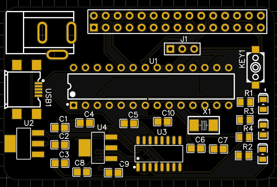
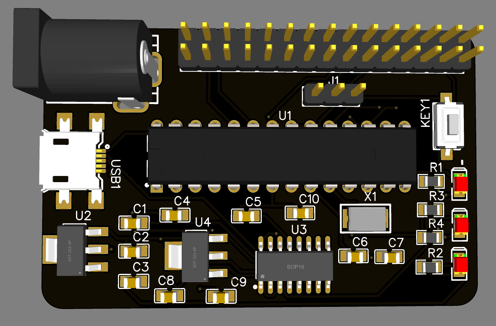
This custom controller is built around the popular ATmega328 microcontroller and utilizes the FT232 IC for reliable USB-to-UART communication. Designed for embedded systems, this controller offers high flexibility for various IoT, automation, and communication applications. The ATmega328 microcontroller is known for its compact size, low power consumption, and robust performance, while the FT232 IC ensures seamless USB connectivity for easy communication with external devices, including sensors, modules, and other embedded systems.
Key Features & Specifications
- Microcontroller: ATmega328, widely used in Arduino-based projects, offering 32KB of flash memory, 2KB of SRAM, and 1KB of EEPROM.
- USB-to-UART Conversion: FT232 IC provides reliable USB-to-serial communication, ensuring compatibility with a wide range of operating systems (Windows, Linux, macOS).
- USB Interface: Plug-and-play USB connection for easy communication with PCs or other USB-enabled devices.
- Baud Rate Support: Supports a wide range of baud rates for flexible communication options.
- Voltage Compatibility: Operates at both 5V and 3.3V logic levels, making it suitable for a wide variety of projects.
- I/O Pins: ATmega328 microcontroller offers 23 I/O pins, including 6 analog inputs, 14 digital I/O pins, and 1 UART, 1 SPI, and 1 I2C interface.
- Programming Interface: Supports in-circuit serial programming (ICSP) and bootloader-based programming via USB.
- Low Power Consumption: The ATmega328 operates efficiently in low-power modes, ideal for battery-powered or energy-conscious projects.
- Built-in USB-to-Serial Converter: The FT232 IC provides seamless USB-to-serial communication without requiring an additional external USB-to-serial adapter.
- Overcurrent Protection: The controller includes overcurrent protection to safeguard both the microcontroller and USB connection.
- Temperature Range: Operates reliably within a temperature range of -40°C to +85°C, suitable for industrial and outdoor environments.